
Speed reducer for walk assist apparatus

a technology of speed reducer and assistive equipment, which is applied in the direction of mechanical equipment, gearing details, gearing, etc., can solve the problems of poor appearance, increase in overall dimensions of the actuator, and inability to fit the actuator under the user's, so as to reduce the axial thickness of the reduction gear, and reduce the effect of speed

Inactive Publication Date: 2008-07-29
HONDA MOTOR CO LTD
View PDF13 Cites 26 Cited by
  • Summary
  • Abstract
  • Description
  • Claims
  • Application Information

AI Technical Summary

Benefits of technology

The present invention relates to a thin reduction gear for a walking assistance system that can provide a sufficient reduction ratio while reducing the axial thickness of the reduction gear. The invention proposes a reduction gear that includes a input shaft, an output shaft, a first planetary gear mechanism, and a second planetary gear mechanism. The first and second planetary gear mechanisms are arranged in a way that their rotation is reduced in speed by the first and second sun gears and transmitted to the output shaft. This arrangement helps to reduce the axial thickness of the reduction gear compared to a case where the first and second mechanisms are stacked in the axial direction. Additionally, the invention proposes a third and fourth aspect of the reduction gear that includes a third and fourth planetary gear mechanism, respectively. These aspects further improve the appearance of the reduction gear when worn with the walking assistance system.

Problems solved by technology

The above-mentioned conventional walking assistance system includes an actuator integrated with a motor and a reduction gear, and since the reduction gear is required to have a large reduction ratio, there is the problem that the overall dimensions of the actuator increase.
As a result, it becomes difficult to fit the actuator under a user's clothing, and since the actuator is exposed outside the clothing, the appearance is poor.
Although the above-mentioned conventional reduction gear, in which the plurality of planetary gear mechanisms are axially stacked in multiple stages, is excellent in having a large reduction ratio, since the axial dimensions are large, it is not suitable for use in an actuator of a walking assistance system.

Method used


Image

  • Speed reducer for walk assist apparatus
  • Speed reducer for walk assist apparatus
  • Speed reducer for walk assist apparatus

Examples


first embodiment

[0023]the present invention is explained below with reference to FIG. 1 to FIG. 7.

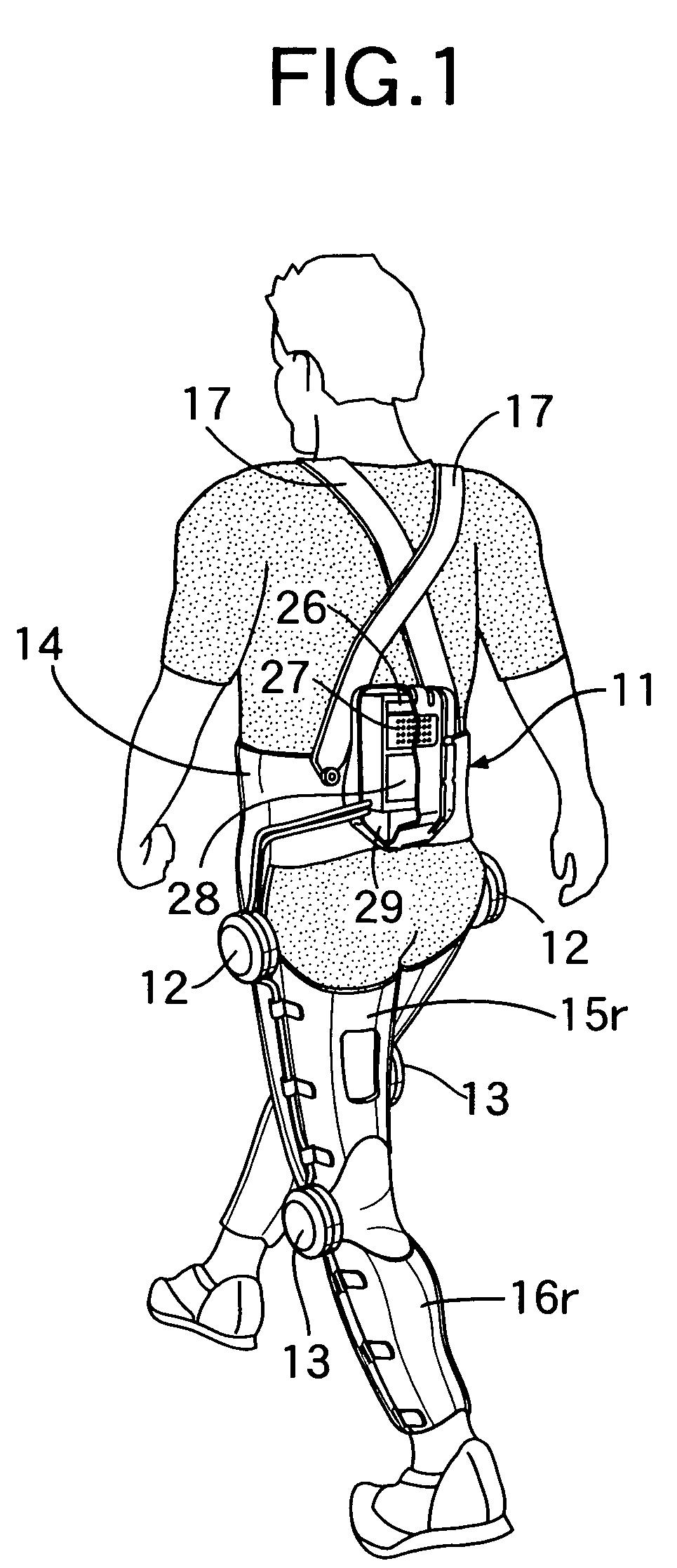
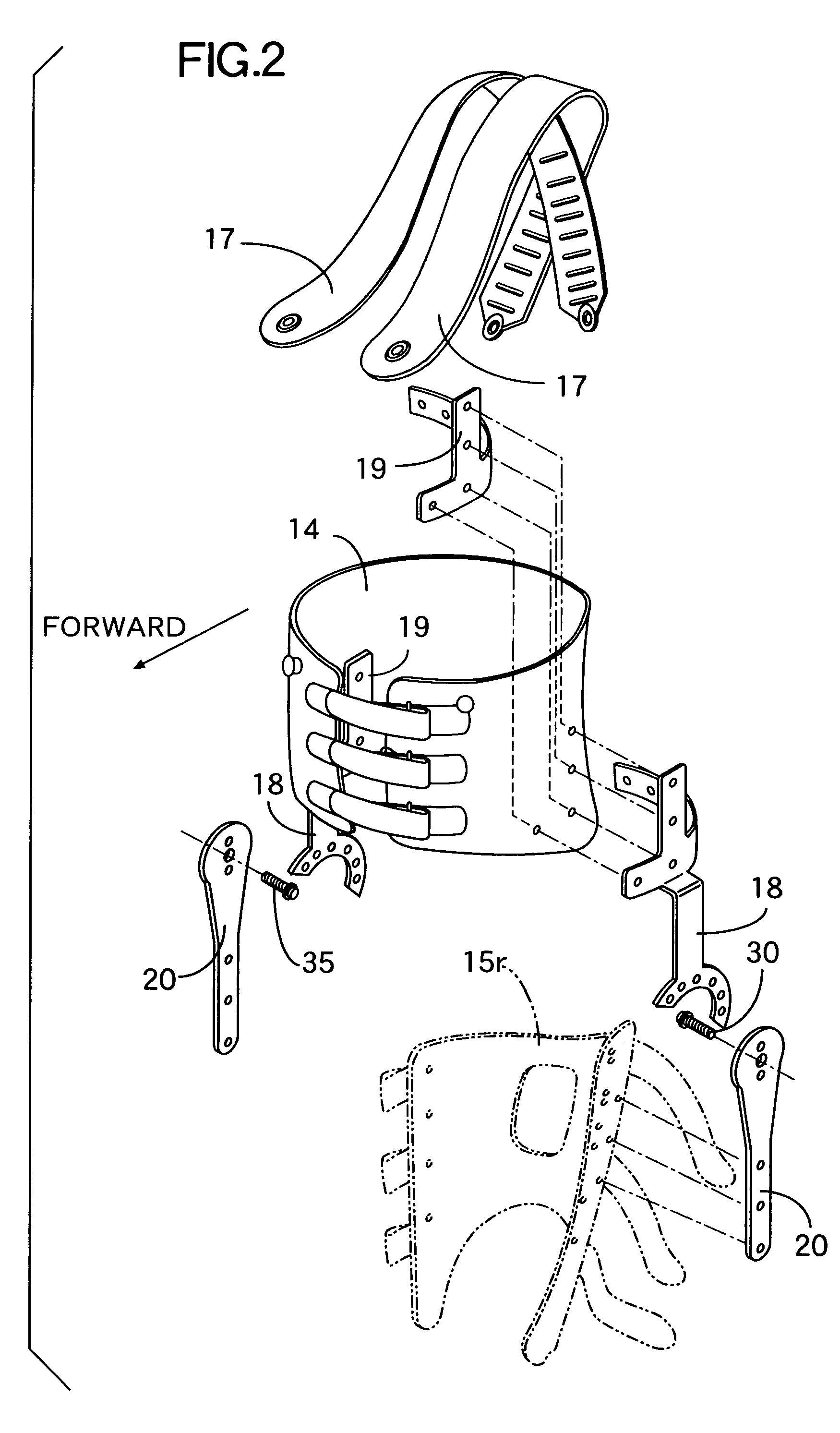
[0024]As shown in FIG. 1 to FIG. 3, a walking assistance system of the present invention includes a backpack 11 carried by a user on the back, a pair of left and right first electric actuators 12 applying a torque to left and right hip joints, a pair of left and right second electric actuators 13 applying a torque to left and right knee joints, an abdominal belt 14 made of a flexible resin and detachably fitted around the user's abdomen, upper leg supports 15f and 15r made of a flexible resin, split into front and rear portions, and detachably fitted around the user's left and right thighs, lower leg supports 16f and 16r made of a flexible resin, split into front and rear portions, and detachably fitted around the user's left and right lower legs, and two suspenders 17 extending from a front part of the abdominal belt 14 and connected to a rear part of the abdominal belt 14 via the user's shoulders. FI...


PUM


Abstract

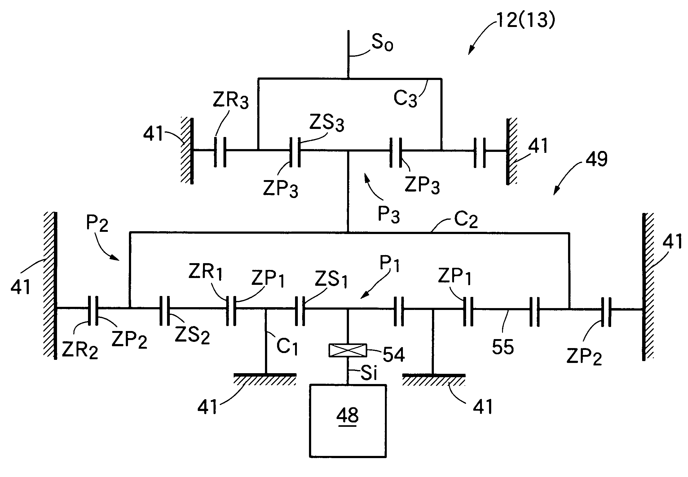
A reduction gear (49) for a walking assistance system is provided that includes first to third planetary gear mechanisms (P1 to P3) between an input shaft (Si) connected to a motor (48) and an output shaft (So), the second planetary gear mechanism (P2) being disposed radially outside the first planetary gear mechanism (P1) connected to the input shaft (Si), and the third planetary gear mechanism (P3) being disposed outside, in the direction of an axis L, the first planetary gear mechanism (P1). It is therefore possible, while reducing the speed of rotation of the input shaft (Si) in three stages by the first to the third planetary gear mechanisms (P1 to P3) and transmitting the rotation to the output shaft (So), to reduce the thickness of the reduction gear (49) compared with a case in which the first to the third planetary gear mechanisms (P1 to P3) are disposed so as to be stacked in the direction of the axis (L), thereby improving the appearance when a user is fitted with the walking assistance system.

Description

FIELD OF THE INVENTION[0001]The present invention relates to a walking assistance system that assists elderly people with weakened muscle strength or injured people to walk, climb up and down stairs, stand up from a seated posture, sit down from a standing posture, etc. so as to facilitate movement, thus suppressing degradation in muscle strength and correcting the gait mode, and, in particular, it relates to a reduction gear for the walking assistance system.BACKGROUND ART[0002]Such a walking assistance system has already been proposed in Japanese Patent Application No. 2001-109046 related to an application of the present applicant. This walking assistance system includes an electric actuator fitted to user's leg joints (i.e., a hip joint and a knee joint ), and the actuator is operated by supplying electric power from a power source within a backpack carried by the user on the back so as to generate a joint torque for extending / bending each joint, thus assisting the user in carryi...

Claims


Application Information

Patent Timeline
Patent Type & Authority Patents(United States)
IPC IPC(8): F16H57/08A61H1/02A61H3/00F16H1/36F16H1/46
CPCA61H1/0237A61H3/008F16H1/36F16H1/46A61H1/0255A61H3/00A61H2201/1472Y10S475/903A61H2201/1215A61H2201/1616A61H2201/1642A61H2201/165A61H2201/1652A61H2201/1676
Inventor KUDOH, HIROSHIKATOH, HISASHI
Owner HONDA MOTOR CO LTD
Learn More