
Electric vehicle

a technology of electric vehicles and electric motors, applied in the direction of electric propulsion mounting, battery/fuel cell control arrangement, electric devices, etc., can solve the problems of contact welding, and inability to perform the function of interrupting electric power, so as to reduce the number of winding turns and reduce the diameter of the winding. , the effect of reducing the number of windings

Inactive Publication Date: 2008-07-29
PANASONIC EV ENERGY CO LTD
View PDF15 Cites 10 Cited by
  • Summary
  • Abstract
  • Description
  • Claims
  • Application Information

AI Technical Summary

Benefits of technology

This configuration prevents simultaneous welding of moving contacts during external impacts, achieving the same impact resistance with reduced spring force, allowing for smaller electromagnetic coil windings and lower costs while maintaining reliability.

Problems solved by technology

When the contacts come into contact again, the contacts are cooled and fixed (short-circuited), and become incapable of performing the function of interrupting electric power.
Thus the contacts are welded and become incapable of performing the function of interrupting electric power.
As described above, for conventional main contactors mounted on electric vehicles such as HEVs, it was necessary to enhance both of two conflicting functions in such a way as to increase the electromagnetic force of the electromagnetic coil as well as increase the spring force of the shaft spring, in order to provide resistance against external impact for the main contactors, and thus there were problems that the sizes of the electromagnetic coil and the shaft spring are increased and the cost is increased.

Method used


Image

  • Electric vehicle
  • Electric vehicle
  • Electric vehicle

Examples


Embodiment Construction

[0023]Hereinafter, preferred embodiments of the present invention will be described with reference to the drawings, taking a hybrid electric vehicle (HEV) as an example.

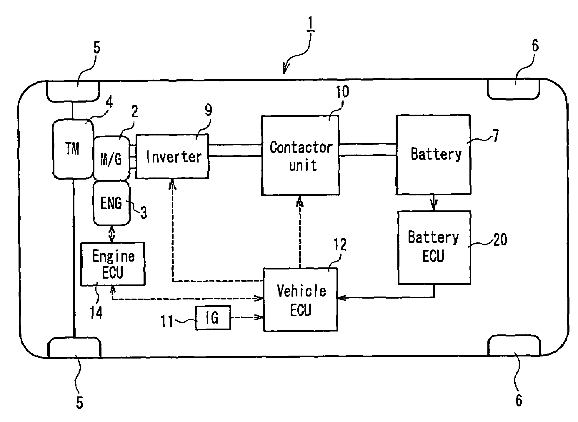
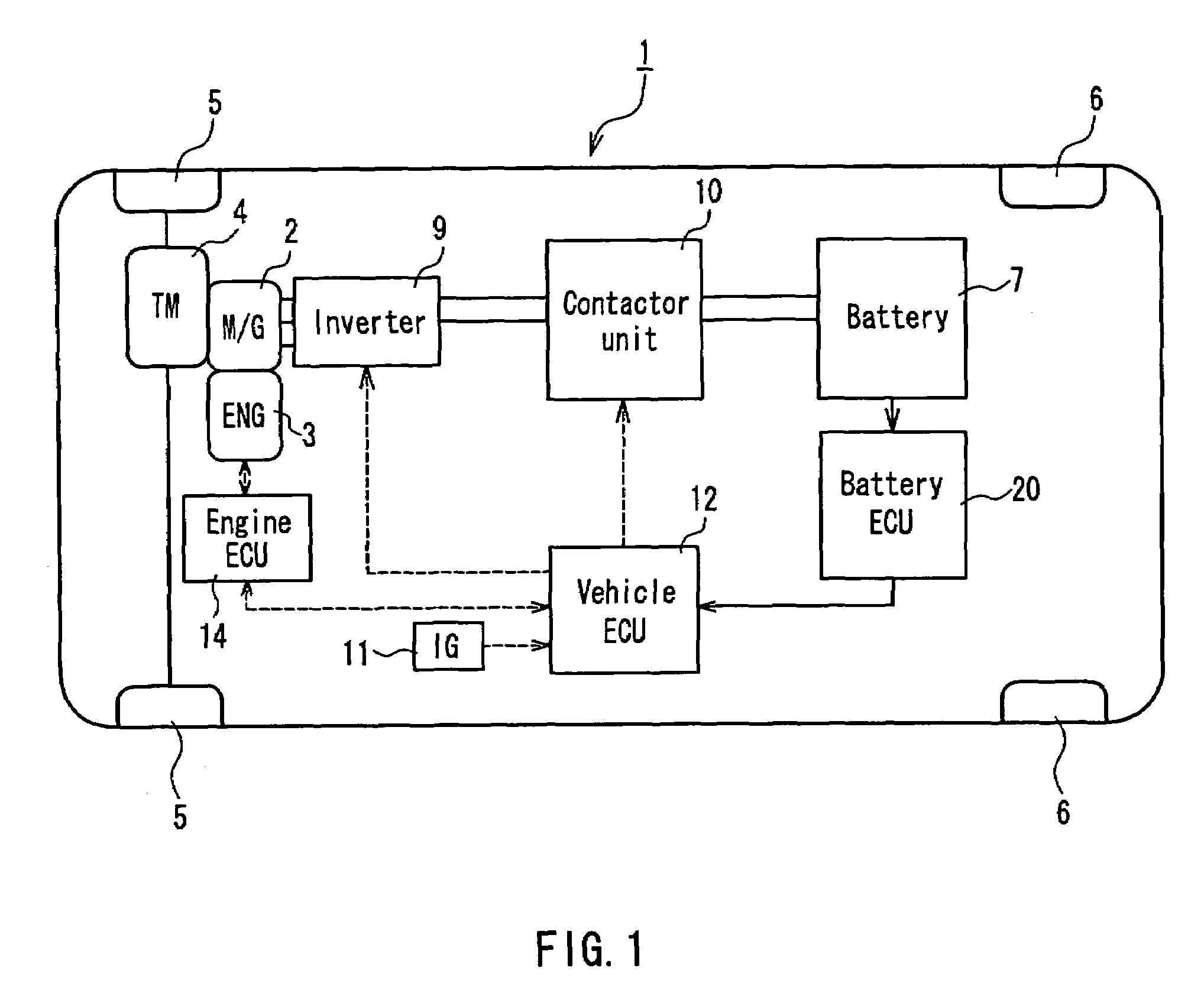
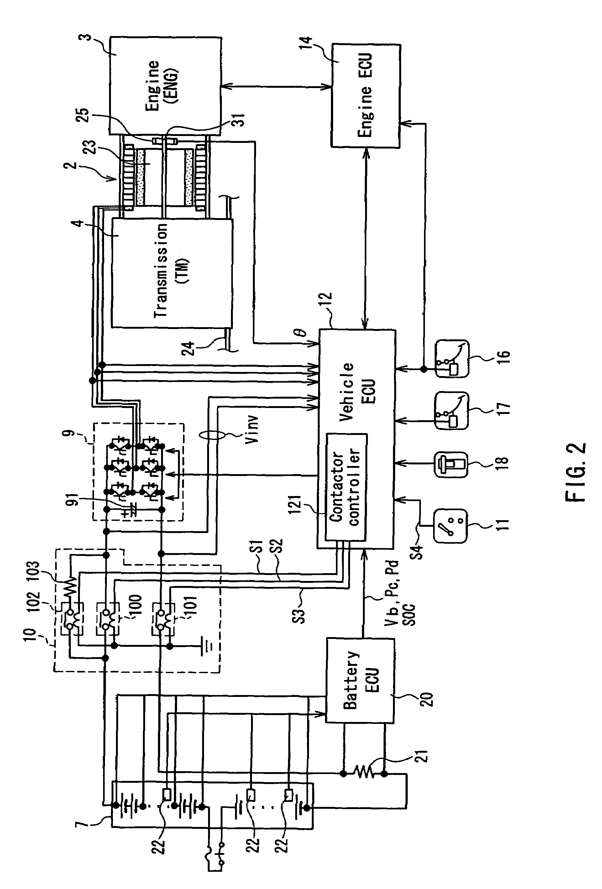
[0024]FIG. 1 is a diagram showing the overall configuration of a HEV serving as the electric vehicle according to an embodiment of the present invention. In FIG. 1, the HEV 1 has a pair of left and right front wheels 5 and 5, which are driving wheels, to which an output of a motor generator (M / G) 2 or an engine (ENG) 3 is transmitted via a transmission (TM) 4, and a pair of left and right rear wheels 6 and 6. A battery pack 7 that is mounted at the rear of the HEV 1 and that outputs, for example, a voltage of 360 V is connected to the motor generator 2 via a contactor unit 10 and an inverter 9. ON / OFF signals of an ignition key switch (IG) 11 are supplied to a vehicle electronic control unit (hereinafter, abbreviated as “vehicle ECU”) 12, and the vehicle ECU 12 controls the contactor unit 10, the inverter 9, and an e...


PUM


Abstract

A positive side main contactor serving as a contact switching device on the positive side, which is connected between a positive electrode terminal of a battery pack and a high potential input terminal of an inverter, and a negative side main contactor serving as a contact switching device on the negative side, which is connected between a negative electrode terminal of the battery pack and a low potential input terminal of the inverter, are arranged so that moving contacts of these are moved forward and backward in directions that are different from each other, e.g. by 90 degrees. Thus, a situation in which the two main contactors are simultaneously turned ON upon external impact can be avoided, and consequently, it is possible to achieve the same impact resistance as was previously possible with a smaller spring force than was previously required. Therefore, it is possible, for example, to reduce the number of turns of the winding in an electromagnetic coil of each of the main contactors or to reduce the winding diameter. The size and the cost of the contact switching device are reduced while maintaining reliability.

Description

BACKGROUND OF THE INVENTION[0001]1. Field of the Invention[0002]The present invention relates to electric vehicles, such as pure electric vehicles (PEVs) and hybrid electric vehicles (HEVs), in particular hybrid electric vehicles having a fuel cell and a secondary cell, that run by converting a dc power from a battery pack, which is a driving power source mounted on such electric vehicles, into an ac power using an inverter and supplying the ac power to a motor. Moreover, the present invention particularly relates to a technique for preventing moving contacts of a positive side main contactor and a negative side main contactor that are provided between the battery pack and the inverter from being welded simultaneously.[0003]2. Description of the Related Art[0004]In so-called hybrid electric vehicles (HEVs) and the like that carry an engine and a motor, there is provided, between a battery pack, which is formed by combining a plurality of secondary cells, and an inverter, which is a ...

Claims


Application Information

Patent Timeline
Patent Type & Authority Patents(United States)
IPC IPC(8): B60K1/00B60K6/28B60K6/48B60K6/547B60L3/00B60W10/08B60W10/26B60W20/00H01H50/04
CPCB60K6/32B60K6/48B60L3/003B60L3/0046B60L11/14B60L11/1864B60K6/365Y02T10/70B60L2210/40B60L2240/445B60L2240/525B60L2240/545B60L2240/549B60L2270/20Y02T10/6221Y02T10/7005Y02T10/7077Y02T90/34Y02T10/7241Y02T10/7061B60L50/16B60L58/13B60L58/14B60L58/18B60L58/21Y02T10/62Y02T10/7072Y02T10/72Y02T90/40
Inventor NAKANISHI, TOSHIAKIKIMURA, TADAO
Owner PANASONIC EV ENERGY CO LTD
Learn More