Multiple discharge ignition control apparatus and method for internal combustion engines
a control apparatus and ignition control technology, applied in the direction of electric ignition installation, mechanical equipment, machines/engines, etc., can solve the problems of increasing the voltage required to hold ignition discharge, increasing the gas around the spark plug, and unable to ensure the required secondary curren
- Summary
- Abstract
- Description
- Claims
- Application Information
AI Technical Summary
Benefits of technology
Problems solved by technology
Method used
Image
Examples
first embodiment
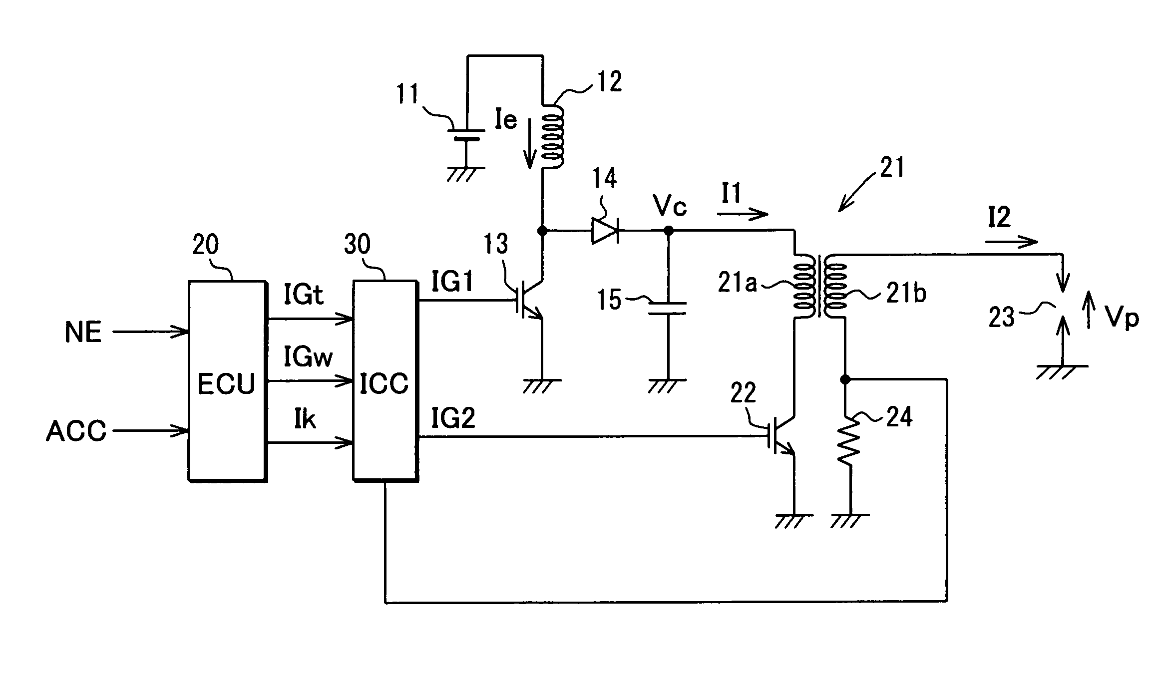
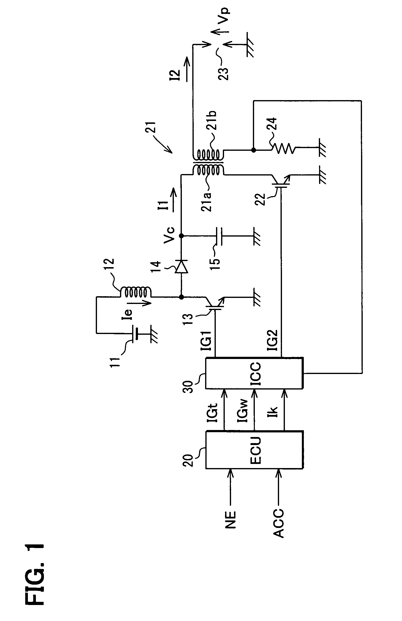
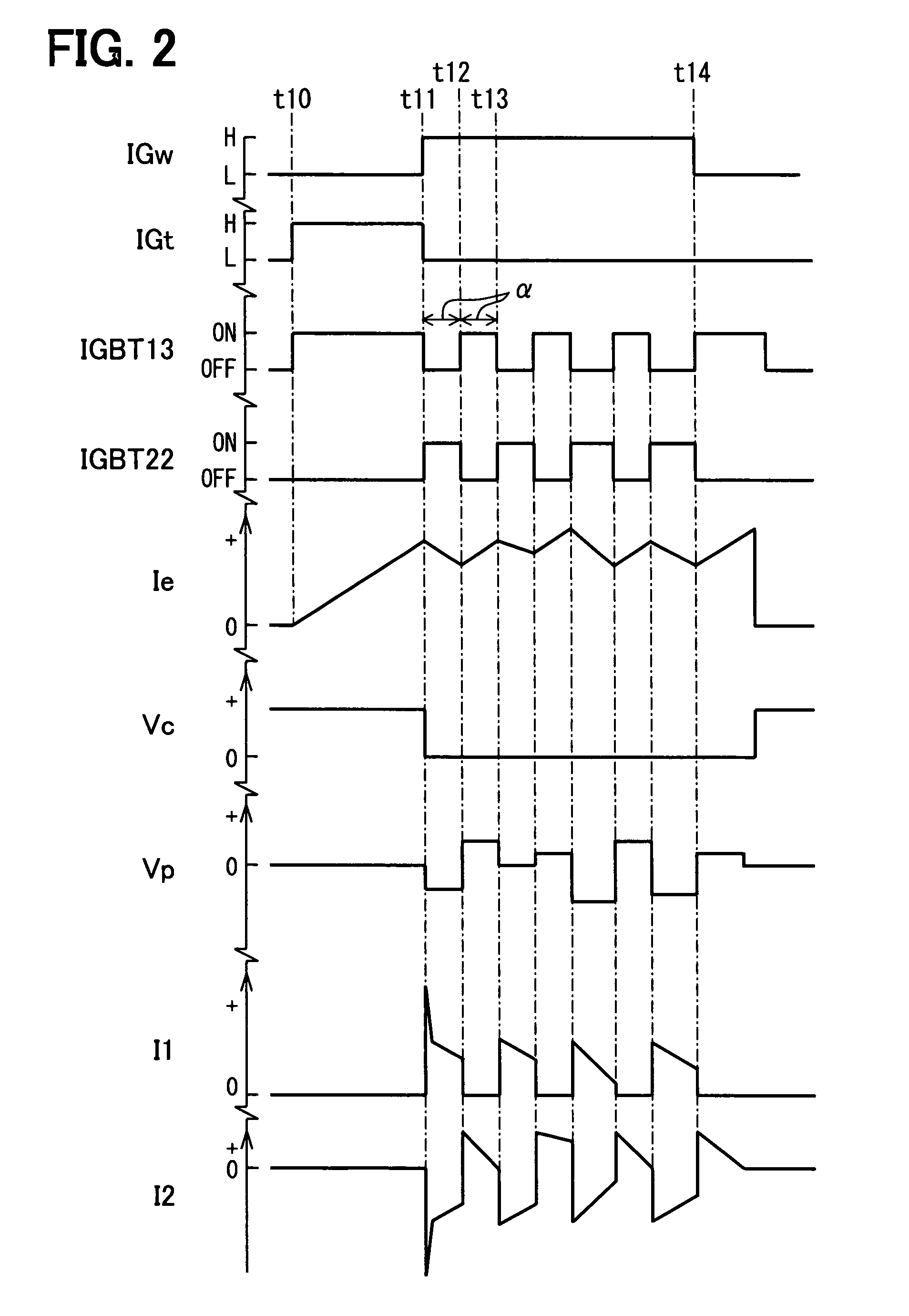
[0029]Referring first to FIG. 1, a battery 11 as a direct-current power source is connected in series with an energy storage coil 12 and a first IGBT 13. When the IGBT 13 is ON, electrical energy is stored in the energy storage coil 12. Between the energy storage coil 12 and the IGBT 13, a capacitor 15 is connected for capacitive discharge through a diode 14. This capacitor 15 is charged with the electrical energy stored in the energy storage coil 12.
[0030]An ignition coil 21 provided for each cylinder of the engine is constructed with a primary coil 21a and a secondary coil 21b. One end of each primary coil 21a is connected with the capacitor 15, and the other end is connected with a second IGBT 22. As a result of this IGBT 22 being turned on / off, the electrical energy stored in the energy storage coil 12 and the capacitor 15 is released, and a primary current I1 is supplied through the primary coil 21a thus energizing the primary coil 21a. One end of each secondary coil 21b is con...
second embodiment
[0048]A second embodiment is constructed to meet ultra-lean burn engine, in which an air-fuel ratio is significantly made lean. Therefore the plug voltage required for effecting ignition discharge is 2 to 5 kV or so and the discharge holding current required for the same is 50 to 100 mA or so. The second embodiment has a DC / DC converter as power supply means for boosting and outputting battery voltage.
[0049]As illustrated in FIG. 7, the battery 11 is connected with a DC / DC converter 41 with an output voltage of Vdc (several tens to a hundred of volts or so). At the same time, the DC / DC converter 41 is connected in series with the primary coil 21a through a diode 42 for reverse-flow prevention. This DC / DC converter 41 may be a conventional booster circuit constructed with an inductor, a transistor, a diode and a capacitor. With this construction, when IGBT 22 is turned on, the output voltage Vdc of the DC / DC converter 41 is applied to the primary coil 21a, and electrical energy is su...
third embodiment
[0055]In a third embodiment shown in FIG. 9A, a DC / DC converter 51 is provided as a power supply means for boosting and outputting battery voltage. Further, an H-bridge circuit is constructed with transistors 52, 53 and IGBTs 22, 54 to supply a current from the DC / DC converter 51 to the primary coil 21a of the ignition coil 21 both in the forward direction and in the reverse direction. By supplying the current through the primary coil 21a both in the forward direction and in the reverse direction by this H-bridge circuit, electrical energy required for ignition discharge is supplied.
[0056]Specifically, the battery 11 is connected with the DC / DC converter 51 with the output voltage Vdc (several tens to a hundred of volts or so). The primary coil 21a is connected to the DC / DC converter 51 through either transistor 52 or 53 and is grounded through either IGBT 22 or 54. With this construction, when the transistor 52 and the IGBT 22 are turned on with the transistor 53 and the IGBT 54 be...
PUM
 Abstract
Description
Claims
Application Information
 - R&D
- Intellectual Property
- Life Sciences
- Materials
- Tech Scout
- Unparalleled Data Quality
- Higher Quality Content
- 60% Fewer Hallucinations
Browse by: Latest US Patents, China's latest patents, Technical Efficacy Thesaurus, Application Domain, Technology Topic, Popular Technical Reports.
© 2025 PatSnap. All rights reserved.Legal|Privacy policy|Modern Slavery Act Transparency Statement|Sitemap|About US| Contact US: help@patsnap.com


