
System and method for reducing a radar interference signal

a radar interference and signal technology, applied in the field of radar systems and methods, can solve the problems of reducing the ability to find the frequency spectrum is overwhelmed, and the frequency signal associated with the target cannot be found in the frequency spectrum

Active Publication Date: 2008-07-22
VALEO RADAR SYST
View PDF71 Cites 28 Cited by
  • Summary
  • Abstract
  • Description
  • Claims
  • Application Information

AI Technical Summary

Benefits of technology

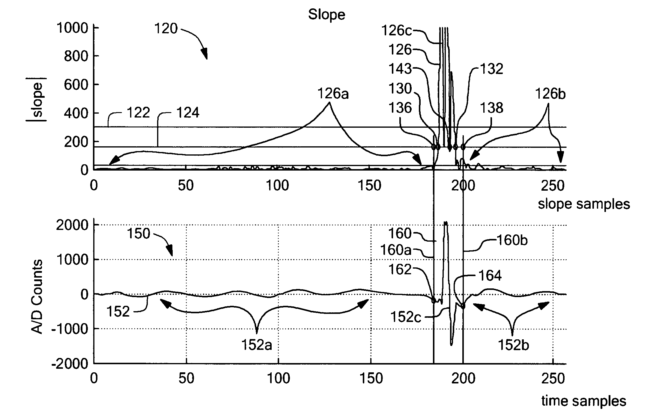
[0018]With these arrangements, a system and technique for detecting an interfering radar signal incident on an FMCW radar is provided. Once the interfering signal is detected, the extent of the interfering signal can be determined and corrupted time samples associated with the interfering signal can be removed from the downconverted signal. This allows the FMCW radar to detect, track, and / or classify a target in the presence of the interfering signal. The system and technique can benefit any FMCW radar that is used in the presence of another system that generates an interfering signal (e.g. another FMCW radar, a police radar gun, a pulse radar, etc.) operating in the same frequency band as the FMCW radar.

Problems solved by technology

However, some types of interfering radar signals can greatly degrade the ability to find the frequency signal associated with the target within the frequency spectrum.
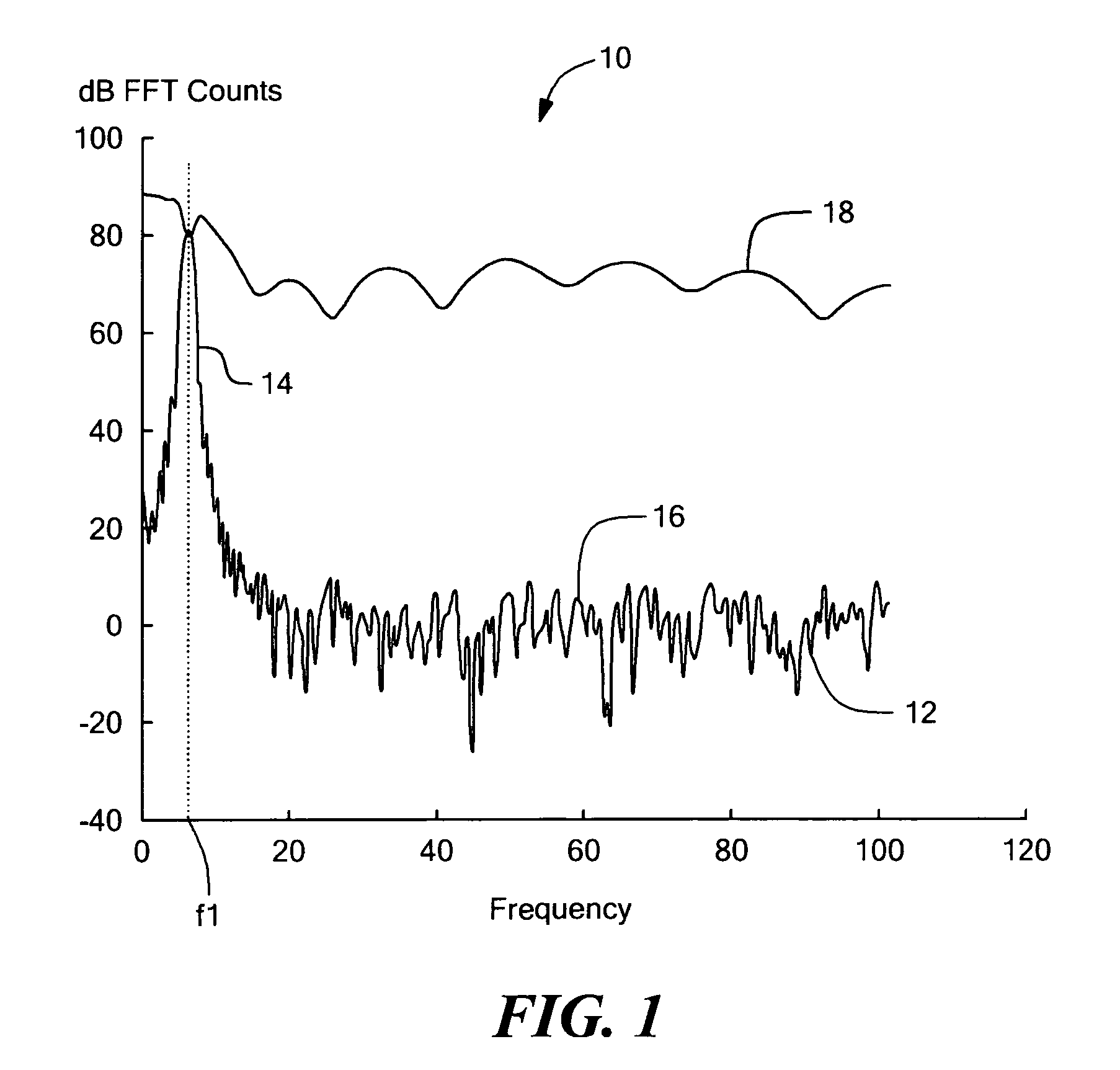
For example, an interfering radar signal at sufficiently high power level and within the swept band (i.e., within the chirp frequency limits) of the FMCW radar can corrupt the time samples of the downconverted signal to such an extent that the resulting frequency spectrum is overwhelmed by the interfering signal and so the frequency signal associated with the target cannot be found in the frequency spectrum.
Susceptibility to noise, including interfering signals, can cause a vehicle radar system to falsely detect an object (i.e., to raise a false alarm rate), and / or, can cause the vehicle radar system to miss a detection of an object (i.e., to have a reduced probability of detection).

Method used


Image

  • System and method for reducing a radar interference signal
  • System and method for reducing a radar interference signal
  • System and method for reducing a radar interference signal

Examples


Embodiment Construction

[0033]Before describing the radar system and method of the present invention, some introductory terms and concepts are discussed. As used herein, the term “frequency modulated continuous wave (FMCW) radar system” is used to describe a particular type of radar system that transmits an FMCW signal, also referred to herein as a “chirp” signal, that changes with time from an intial frequency to a final frequency. The FMCW radar system receives and processes a return signal from a target, which also has the chirp characteristics. As used herein, the terms “downconverted signal” and “video signal” are used to describe an output of a mixer circuit used in a receive portion of the FMCW radar system. The downconverted signal is representative of a frequency difference between the transmitted radar signal and the return signal from the target. Where a return signal substantially from but one target is received, the downconverted signal can have a “beat frequency” indicative of a largest ampli...


PUM


Abstract

A system and method are provided to reduce an interfering signal in a radar return signal for a frequency modulated continuous wave (FMCW) radar. Once the interfering signal is detected, an extent of the interfering signal is determined and the interfering signal is removed from the radar return signal. This allows the radar to detect a target in the presence of the interfering signal. The system and method can benefit any FMCW radar that is within the range of an interfering radar source (e.g. another FMCW radar, a police radar gun, a pulse radar, etc.) operating in the same frequency band as the FMCW radar.

Description

CROSS-REFERENCE TO RELATED APPLICATIONS[0001]Not applicable.STATEMENTS REGARDING FEDERALLY SPONSORED RESEARCH[0002]Not applicable.FIELD OF THE INVENTION[0003]This invention relates generally to radar systems and methods and, more particularly, to a radar system and method that can reduce or eliminate an interfering signal that may be present in a radar return signal.BACKGROUND OF THE INVENTION[0004]As is known in the art, a frequency modulated continuous wave (FMCW) radar transmits a radar signal at a transmitted frequency that is continuously changing. In order to identify a range to a target, the FMCW radar measures a difference in frequency between a received radar signal, which is returned as an echo from the target, and the transmitted frequency. The difference in frequency is associated with a time delay between the transmitted signal and the received signal, i.e., a time that it takes the transmitted signal to reach the target and to return back to the radar.[0005]In typical ...

Claims


Application Information

Patent Timeline
Patent Type & Authority Patents(United States)
IPC IPC(8): G01S13/34G01S7/36G01S13/931
CPCG01S7/023G01S13/931G01S7/354G01S2007/356G01S7/356
Inventor KELLY, JR., THOMAS M.AEDER, R. GREGORYWOODINGTON, WALTER GORDON
Owner VALEO RADAR SYST
Learn More