Image projection system

Inactive Publication Date: 2008-07-22
ASIA OPTICAL CO INC
View PDF4 Cites 8 Cited by
  • Summary
  • Abstract
  • Description
  • Claims
  • Application Information

AI Technical Summary

Benefits of technology

[0009]An object of the present invention is to provide an image projector system, which solves the problem of color shifting caused by LED based light sources.
[0011]The present invention adopts the dichroic mirror to decompose a high-luminance second color light into the third color light and the fourth color light to match the luminance level of the first color light for effecting balance among different colors. To compare with the conventional devices, the present invention fully uses the second color light, and has good performance in efficiency.

Problems solved by technology

However, the UHP has a very high energy consumption is very huge, which in turn generates a great amount of heat.
The lifetime of the UHP lamp is often effected by the huge and intense heat and is thus short (about 1,000-3,000 Hours) so that it needs frequent maintenance and replacement.
In addition, and the UHP lamp is so expensive that the overall cost of the projector is largely increased.
This leads to a low efficiency of light utilization.
However, the conventional projectors using LEDs as light sources surfer drawbacks of color shifting.
This causes problems of color shifting.
Thus, the projector has to set light valve elements to adjust the luminance of the red LED and the green LED, which lows down the efficiency of light utilization.
As the luminance of the three LEDs is different from each other, the chromatic images generated by such a projector often suffer color unbalance.

Method used


Image

  • Image projection system
  • Image projection system
  • Image projection system

Examples


Embodiment Construction

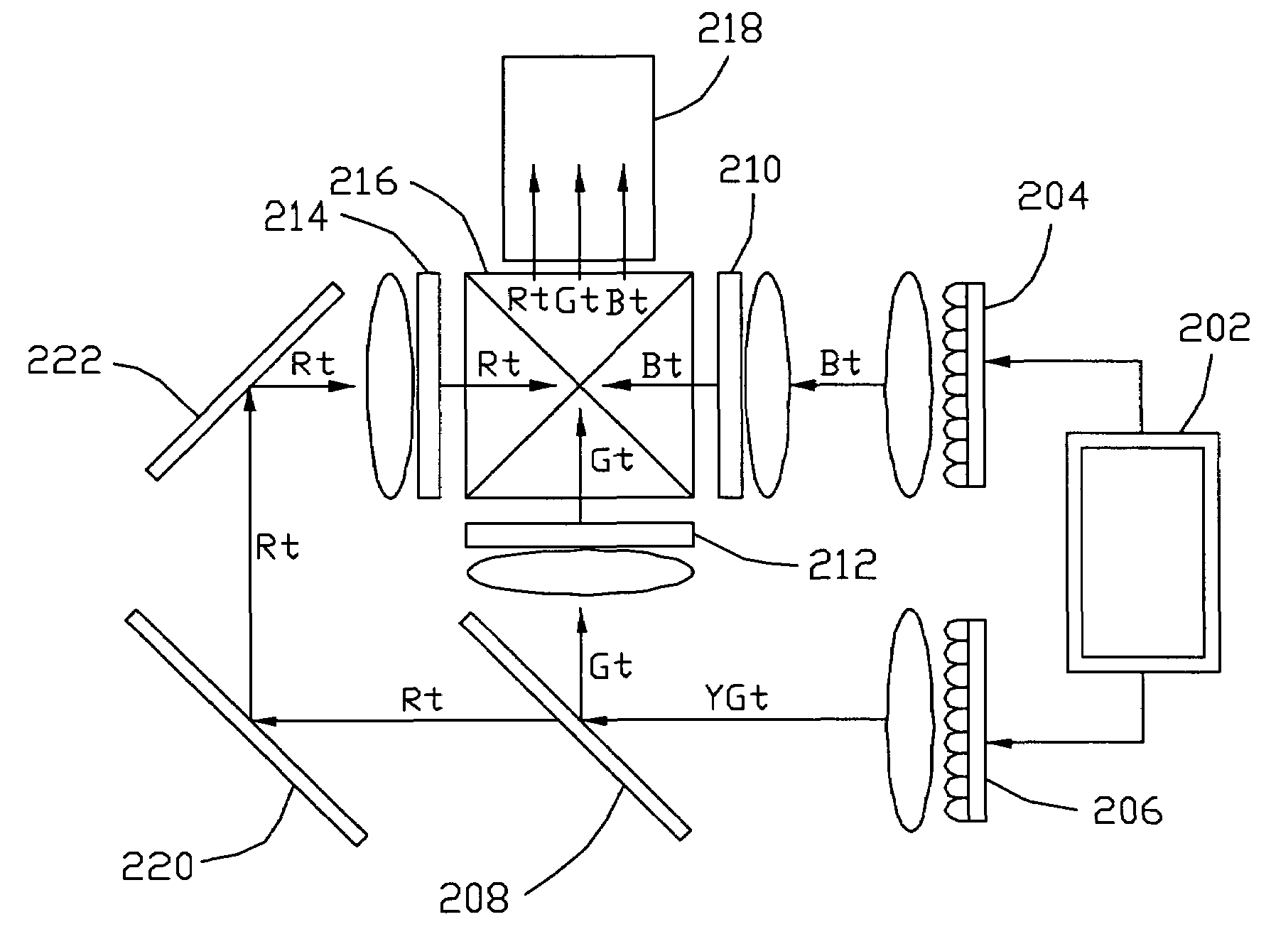
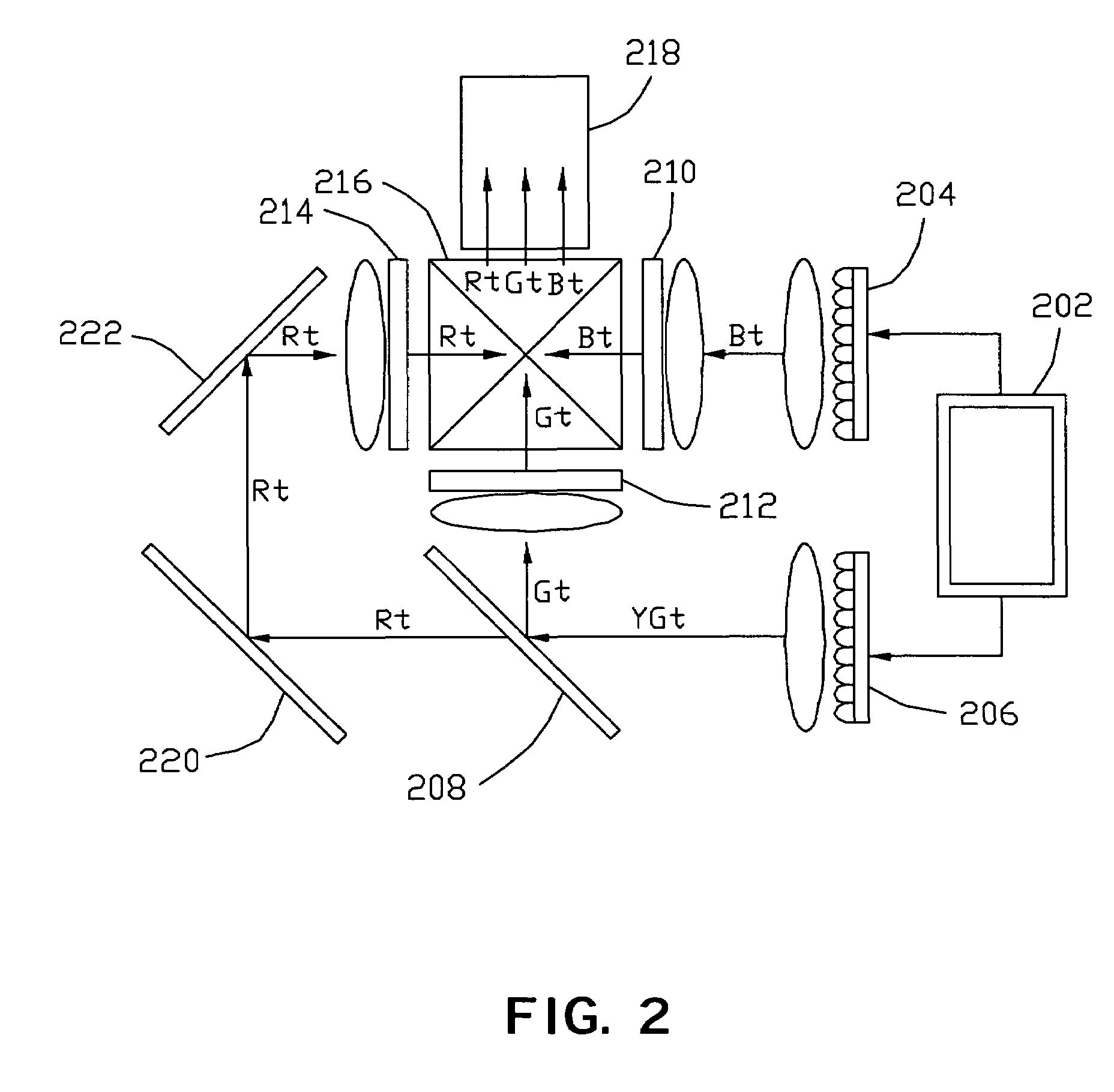
[0015]With reference to the drawings and in particular to FIG. 1, an image projector system in accordance with the present invention comprises an LED controller 202, a first LED 204 emitting a blue light (Bt, first color light), a second LED 206 emitting a yellow-green light (YGt, second color light), a dichroic mirror 208 capable to decompose the yellow-green light into a green light (Gt, third color light) and a red light (Rt, fourth color light), a plurality of liquid crystal light valves 210, 212, 214 used to adjust the luminance of the color lights, an x-cube 216 that combines the different color lights, and a projector lens 218. The projector further comprises first and second mirrors 220, 222 to change the path of the red light.

[0016]The LED controller 202 is a diode driver, which drives the first and the second LEDs 204 and 206 to emit color lights. The LED controller 202 also controls the operation of the liquid crystal light valves 210, 212, 214. The blue light emitted fro...


PUM


Abstract

An image projector system includes an LED controller and first and second LEDs, a dichroic mirror. The LED controller controls the first and the second LED to emit first and second color lights, respectively. The second color light is of high luminance and is decomposed by a dichroic mirror into third and forth color lights having luminance close to that of the first color light. Each color light is guided through a light valves to adjust the spectral transmittance of the color light. A light-combining device, such as an x-cube, receives and combines the first color light, the third color light, and the forth color light, to form light images, and transmits the images to a display through a projector lens.

Description

BACKGROUND OF THE INVENTION[0001]1. Field of the Invention[0002]The present invention relates to an image projection system, and more particularly, to an image projection system having multiple color light sources.[0003]2. Description of the Related Arts[0004]Multimedia projectors usually use an ultra high performance lamp (UHP lamp) as a light source. The UHP lamp has advantages of high efficient and high luminance, which has good performance in the light flux of the projectors. However, the UHP has a very high energy consumption is very huge, which in turn generates a great amount of heat. The lifetime of the UHP lamp is often effected by the huge and intense heat and is thus short (about 1,000-3,000 Hours) so that it needs frequent maintenance and replacement. In addition, and the UHP lamp is so expensive that the overall cost of the projector is largely increased. Further, the UHP lamp is a white light source, and thus, the projector needs an additional color filter to decompose...

Claims


Application Information

Patent Timeline
IPC IPC(8): G03B21/00F21V7/04G02B27/12G02B27/14G02F1/1335G03B21/20G03B21/26H01L33/00H04N5/74
CPCH04N9/315G03B33/12G03B21/2033Y10S362/80
Inventor LU, CHIEN-FENG
Owner ASIA OPTICAL CO INC
Why Eureka
Try Eureka