Method and system for controlling radiation intensity of an imaging system

a radiation intensity control and imaging system technology, applied in the field of imaging systems, can solve the problems of only needing to be exposed to radiation at a reduced intensity, and conventional radiographic or fluoroscopic imaging systems have drawbacks

Active Publication Date: 2008-07-15
GENERAL ELECTRIC CO
View PDF5 Cites 3 Cited by
  • Summary
  • Abstract
  • Description
  • Claims
  • Application Information

AI Technical Summary

Benefits of technology

[0005]There exists a need to provide a system and method of controlling a spatial distribution of radiation intensity which addresses the drawbacks described above. The control system should require minimal user input or intervention and minimize distortion of the acquired images. The system should produce the desired reduction in radiation intensity effect for a wide range of imaging techniques, anatomies, and projection angles with minimal delays in the workflow in the operating room. The system should also allow acquisition of images in fast succession. As projections through the anatomy change, the system should be able to readily reconfigure the intensity of the radiation beam. The system should not require an increase in the size of the imaging system or reduce the field of view of the imaging system. The system should not reduce continuous use of the imaging system. The above-mentioned needs are addressed by the embodiments of a apparatus and method described in the following description.

Problems solved by technology

However, conventional radiographic or fluoroscopic imaging systems have drawbacks.
However, exposure to reduced intensities of radiation may only be needed to adequately image an area of interest (e.g., thinner portions) of the image subject, or to acquire an image for reference only that does not require high spatial or gray scale resolution, or where little change occurs from frame to frame of the imaged subject.

Method used


Image

  • Method and system for controlling radiation intensity of an imaging system
  • Method and system for controlling radiation intensity of an imaging system
  • Method and system for controlling radiation intensity of an imaging system

Examples


Embodiment Construction

[0044]In the following detailed description, reference is made to the accompanying drawings that form a part thereof, and in which is shown by way of illustration specific embodiments that may be practiced. These embodiments are described in sufficient detail to enable those skilled in the art to practice the embodiments, and it is to be understood that other embodiments may be utilized and that logical, mechanical, electrical and other changes may be made without departing from the scope of the embodiments. The following detailed description is, therefore, not to be taken as limiting the scope of the invention.

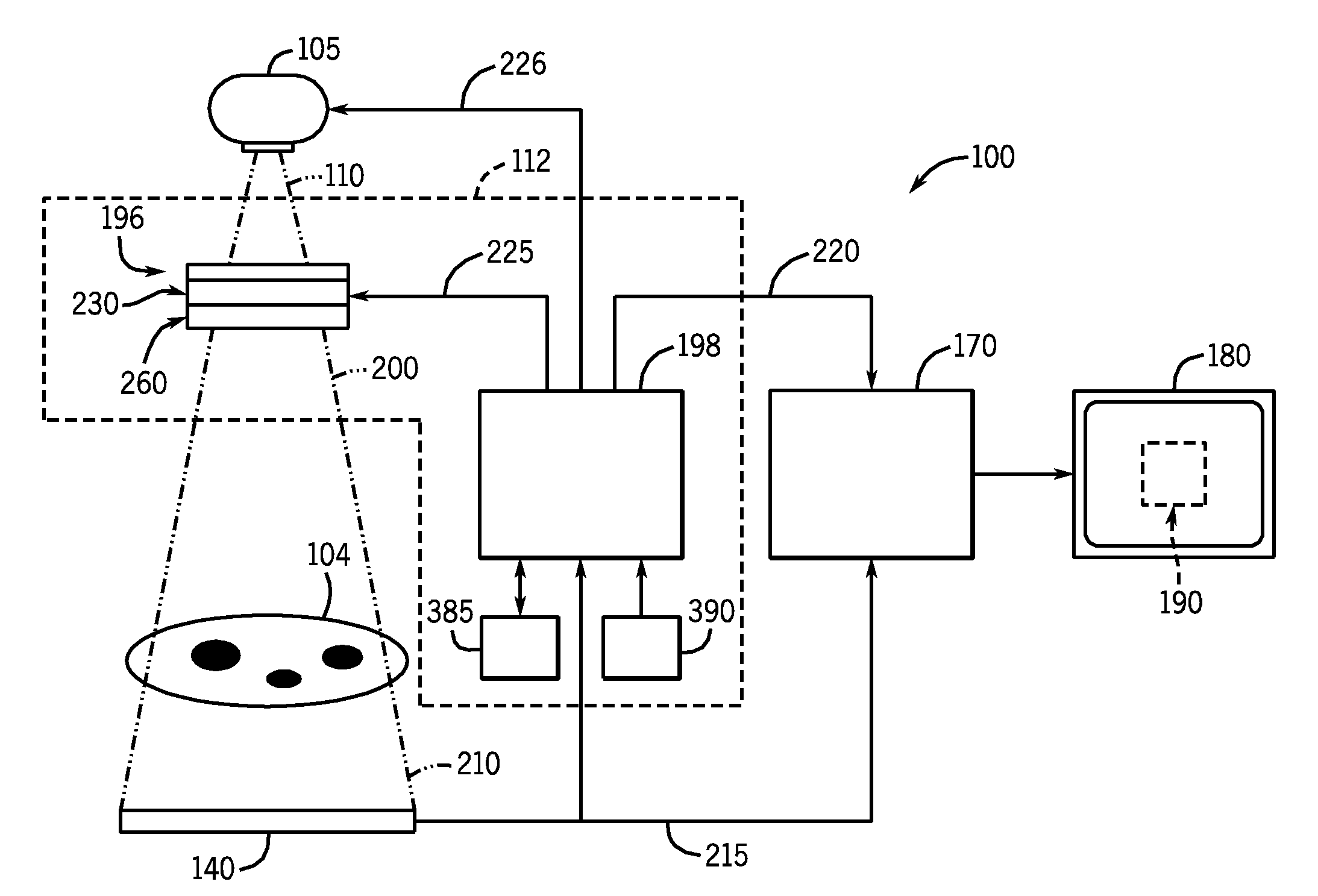
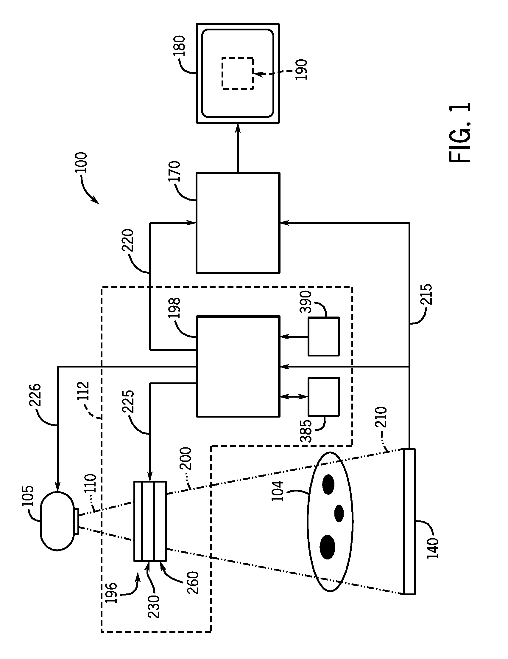
[0045]FIG. 1 illustrates a schematic diagram of an embodiment of an imaging system 100 operable to generate a radiological image of a subject 104. The illustrated imaging system 100 performs radiological imaging by passing X-rays through the subject 104. Yet, the type of imaging employed by the imaging system 100 can vary.

[0046]The imaging system 100 generally includes a radi...


PUM

PropertyMeasurementUnit
transmittanceaaaaaaaaaa
frequencyaaaaaaaaaa
frequency transmittanceaaaaaaaaaa

Abstract

A system for and a method of controlling a spatial distribution of radiation intensity in a beam of radiation is provided. The system includes a control device located to receive the initial beam of radiation from the radiation source. The control device includes a first radiation absorbing structure located at a position in generally superposing alignment relative a position of a second radiation absorbing structure. Each first and second radiation absorbing structure is operable to independently articulate. The modulator configuration signal is operable to cause adjustment of the position of at least one of the first and second radiation absorbing structures relative to the other so as to selectively adjust a spatial distribution of radiation intensity of a modulated beam.

Description

BACKGROUND OF THE INVENTION[0001]This subject matter herein generally relates to an imaging system and more particularly to a method and system for controlling an intensity of a radiation beam employed in the imaging system. The method and system for controlling radiation intensity may be used in applications related to medical and industrial imaging.[0002]A certain conventional radiation imaging system generally includes an radiation source configured to project a beam of electromagnetic radiation toward a subject being imaged. The radiation beam is typically collimated so as to pass through a region of interest of a subject being imaged, such as a patient. As the radiation beam passes through the imaged subject, the imaged subject attenuates the radiation beam intensity. Upon passing through the imaged subject, the attenuated radiation beam impinges upon an array of radiation detectors. The intensity of the radiation beam received at the array of radiation detectors is dependent u...

Claims


Application Information

Patent Timeline
Patent Type & Authority Patents(United States)
IPC IPC(8): G01N23/04
CPCG21K1/10
Inventor YATSENKO, DIMITRI V
Owner GENERAL ELECTRIC CO
Why Eureka
Try Eureka