Narrow bandpass filter assemblies for solar telescopes
a filter assembly and solar telescope technology, applied in the field of narrow bandpass filter assembly for solar telescopes, can solve the problems of increasing loss, increasing the cost of filter assembly construction, and increasing the safety, stability and physical construction of the filter assembly, so as to achieve low cost, high efficiency, and low transmittance.
- Summary
- Abstract
- Description
- Claims
- Application Information
AI Technical Summary
Benefits of technology
Problems solved by technology
Method used
Image
Examples
example 1-3
[0090]The transmittance and bandwidth characteristics of each element, and of the combined optical assembly, were measured on a custom-built high-resolution spectrophotometer with a resolving power of 0.0023 nm. The spectrophotometer was calibrated for wavelength accuracy using both hydrogen and deuterium atomic emission line sources.
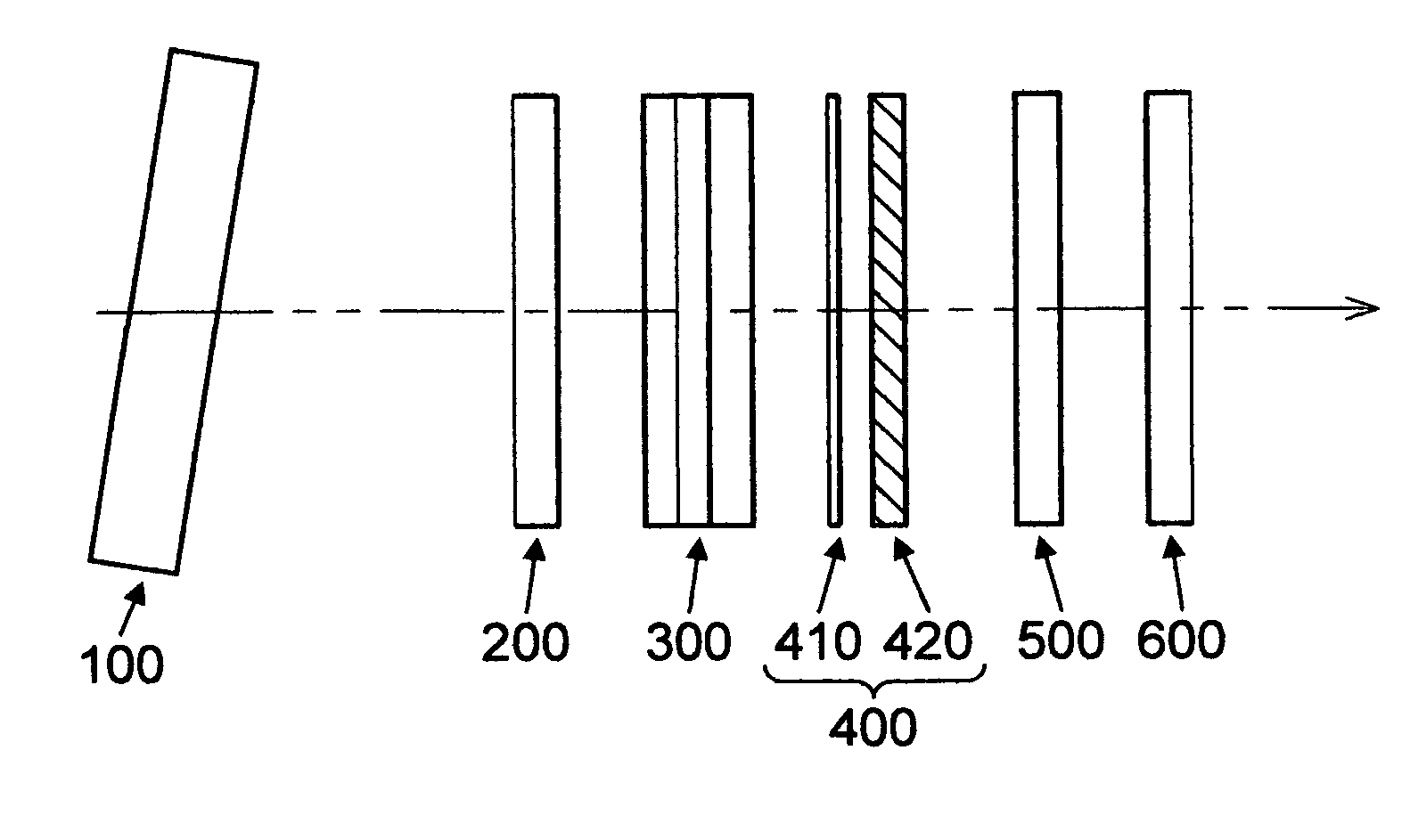
[0091]The optical assembly outlined in FIG. 1 was created with the optical elements described below, in their order of assembly from the light entrance path. In these examples, all elements were joined with an optical couplant.
[0092]A pre-filter with a measured transmittance of 94%, consisting of Schott RG610 glass coated on the entry surface with a broadband AR with a minimum in reflectance centered at 656.3 nm, and on the exit surface with a dichroic heat reflector with cutoff from 715 nm to beyond 1 micron.
[0093]A broadband AR (bandwidth of 430-680 nm, with a measured reflectance of 0.25% at 656 nm).
[0094]A blocker / trimmer filter consisting of a diel...
examples 6-10
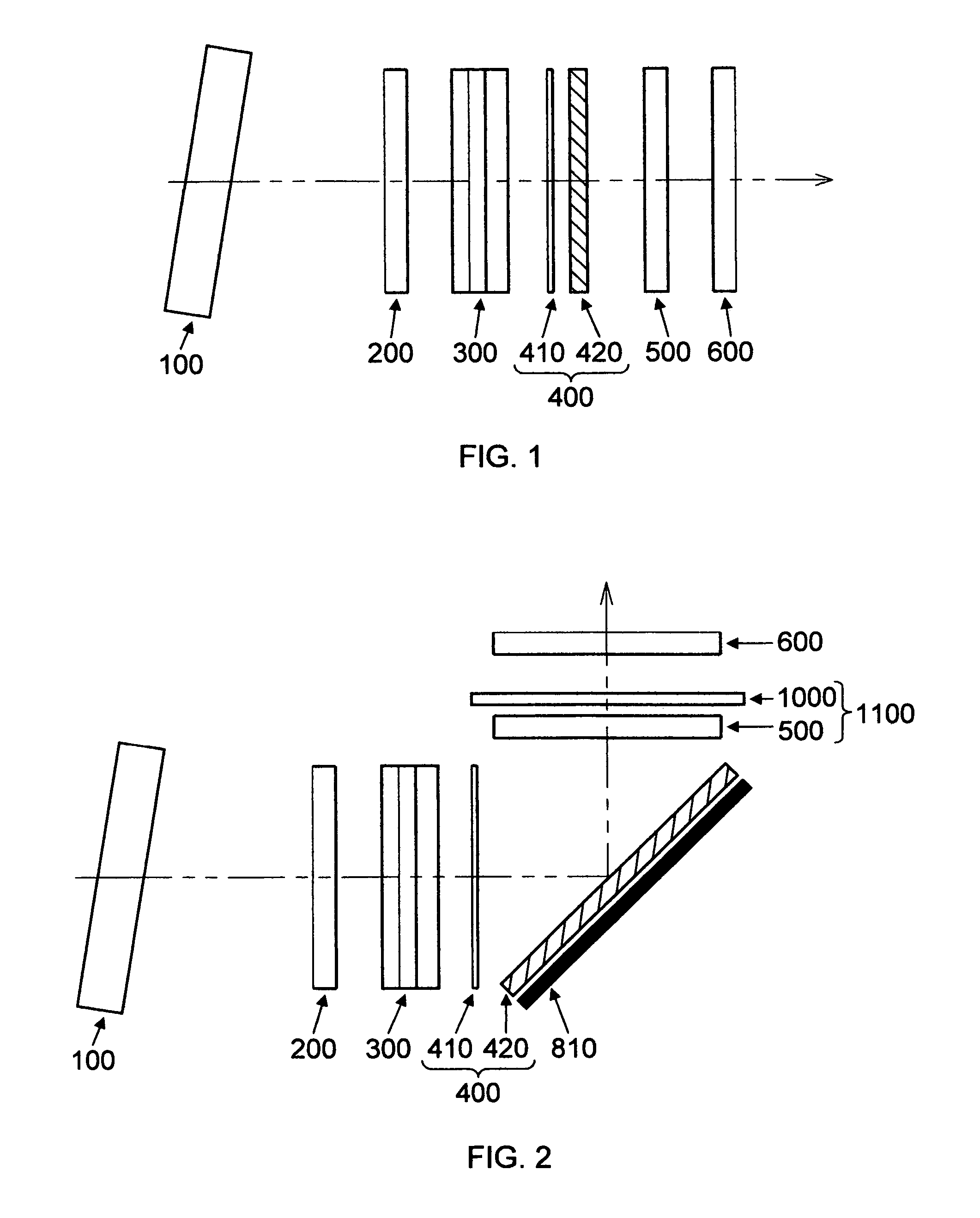
[0101]These are theoretical examples illustrating the use of a polarizing beamsplitter, in the configuration of optical elements outlined in FIG. 2.[0102]Using the following optical elements:[0103]Pre-filter with Transmittance of 94%, as described in examples 1-3.[0104]AR filters at the entrance and exit of the optical path, with reflectance of 0.25% at 656 nm, as in Examples 1-3.
[0105]Blocker / trimmer filter with transmittance of 50% and FWHM of 1.3 nm, as described in Examples 1-3, or alternately, a theoretical blocker / trimmer filter with a FWHM of 1.0 nm and theoretical transmission of 45%.[0106]λ / 4 plate with a 164 nm retardance value.[0107]Polarizing beamsplitter cube with 94% theoretical reflection for the p-state.[0108]Three absorbing, ruby red mica etalons, with different bandpass widths and transmittance values, as described in Examples 1-3, or alternately, theoretical lower transmittance etalons with the same bandwidth and transmittance values.
[0109]The expected performance...
examples 11-13
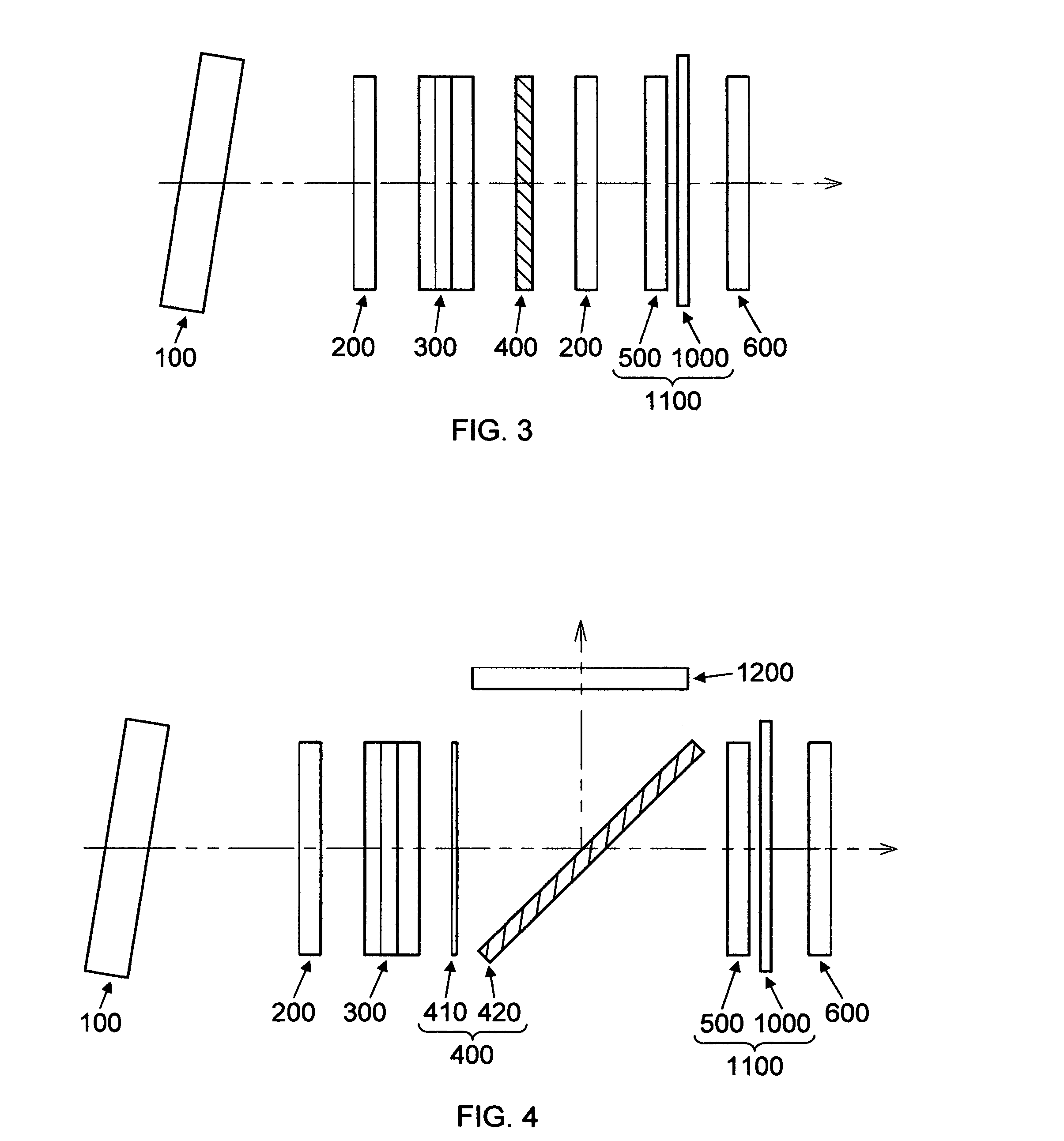
[0111]The following theoretical examples illustrate the use of the heated etalon construct outlined in FIG. 3. The optical elements for these Examples are as follows:[0112]Pre-filter with Transmittance of 94%, as described in Examples 1-3.[0113]AR filters at the entrance and exit of the optical path, and just before the heated etalon construct, each with reflectance of 0.25% at 656 nm, as described in Examples 1-3.[0114]Blocker / trimmer filter with transmittance of 50% and FWHM of 1.3 nm, as described in Examples 1-3.[0115]Achromatic circular polarizer with transmittance of 88.2%, as described in Examples 1-3.[0116]Three theoretical absorbing mica or controlled lower transmittance etalons, with one side coupled to the thermally conductive optical element, and one side exposed to air. Coupling eliminates one air interface and therefore results in slightly higher transmission and slightly wider bandpasses for any given starting design.[0117]Thermally conductive optical element of ITO c...
PUM
 Abstract
Description
Claims
Application Information
 - R&D
- Intellectual Property
- Life Sciences
- Materials
- Tech Scout
- Unparalleled Data Quality
- Higher Quality Content
- 60% Fewer Hallucinations
Browse by: Latest US Patents, China's latest patents, Technical Efficacy Thesaurus, Application Domain, Technology Topic, Popular Technical Reports.
© 2025 PatSnap. All rights reserved.Legal|Privacy policy|Modern Slavery Act Transparency Statement|Sitemap|About US| Contact US: help@patsnap.com


