
Outer core assembly structure of linear motor

a technology of outer core and assembly structure, which is applied in the direction of positive displacement liquid engine, piston pump, magnetic circuit shape/form/construction, etc., can solve the problems of inability to achieve the stable connection complicated manufacturing process of the reinforcing member b>27/b>, and the conventional linear motor. achieve the effect of reducing assembly costs, easy and convenient alignment of the first and second outer core blocks, and easy and convenient assembly

Inactive Publication Date: 2008-07-08
LG ELECTRONICS INC
View PDF9 Cites 4 Cited by
  • Summary
  • Abstract
  • Description
  • Claims
  • Application Information

AI Technical Summary

Benefits of technology

The present invention provides an outer core assembly structure of a linear motor that allows for easy and convenient assembly of the outer core, reducing assembly costs. The structure includes at least one outer core with first and second outer core blocks composed of multiple stacked core sheets, with at least one of the core sheets being an extended core sheet. The extended core sheet is preferably stacked on the outermost side of the core sheets and is secured to the outer core using fixing members. The outer core assembly structure also includes a cylinder block and stator cover that are securely connected to each other in the axial direction, providing stability to the outer core. Additionally, the outer core includes a plurality of radially disposed outer cores along a bobbin, further reducing assembly costs.

Problems solved by technology

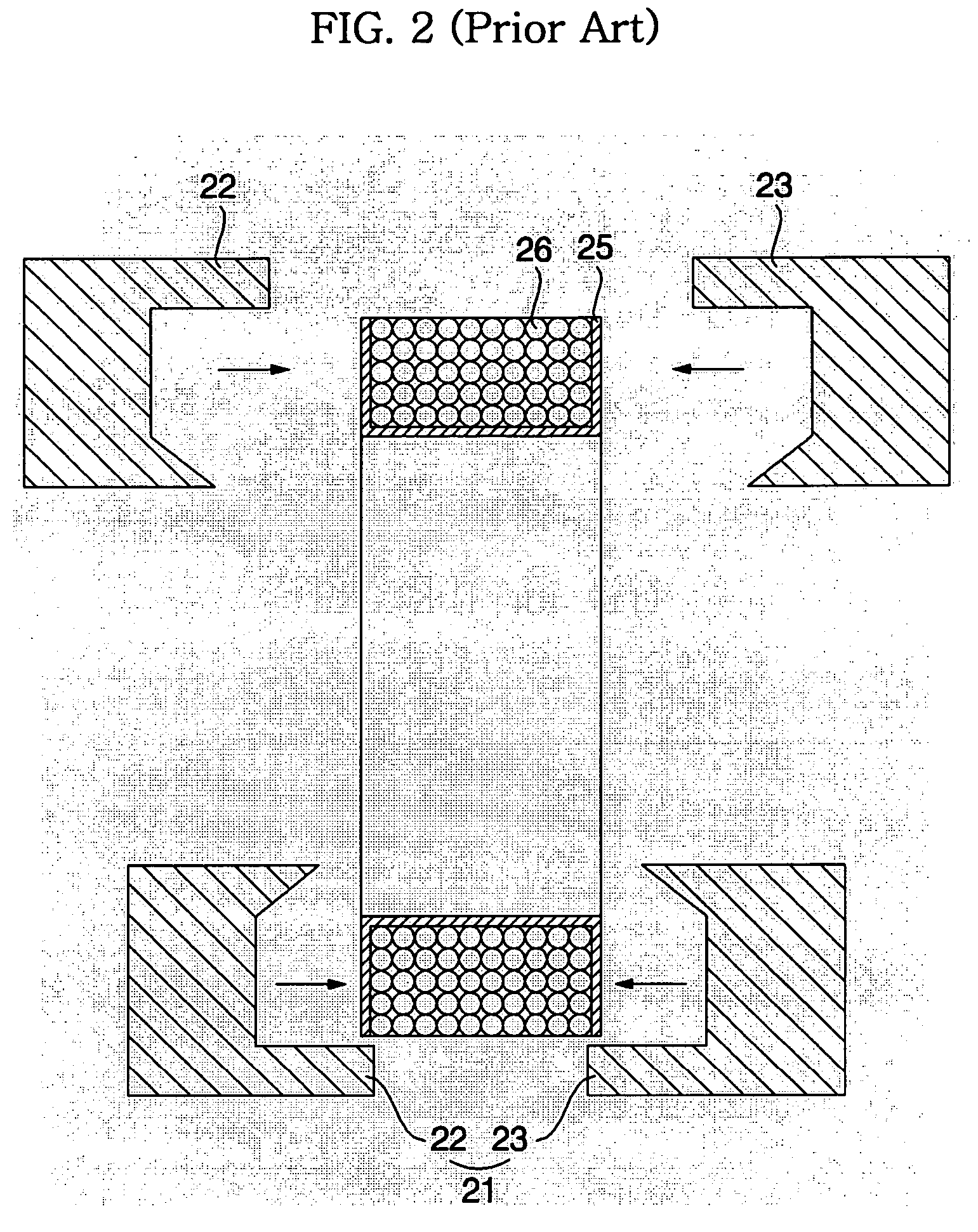
However, the conventional linear motor has the following problems.
Consequently, stable connection of the first and second outer core blocks is not accomplished.
The manufacturing process of the reinforcing member 27 is very complicated, and quality control of the reinforcing member is difficult.
As a result, the manufacturing costs of the linear motor are increased.

Method used


Image

  • Outer core assembly structure of linear motor
  • Outer core assembly structure of linear motor
  • Outer core assembly structure of linear motor

Examples


Embodiment Construction

[0041]Now, a preferred embodiment of the present invention will be described in detail with reference to the accompanying drawings.

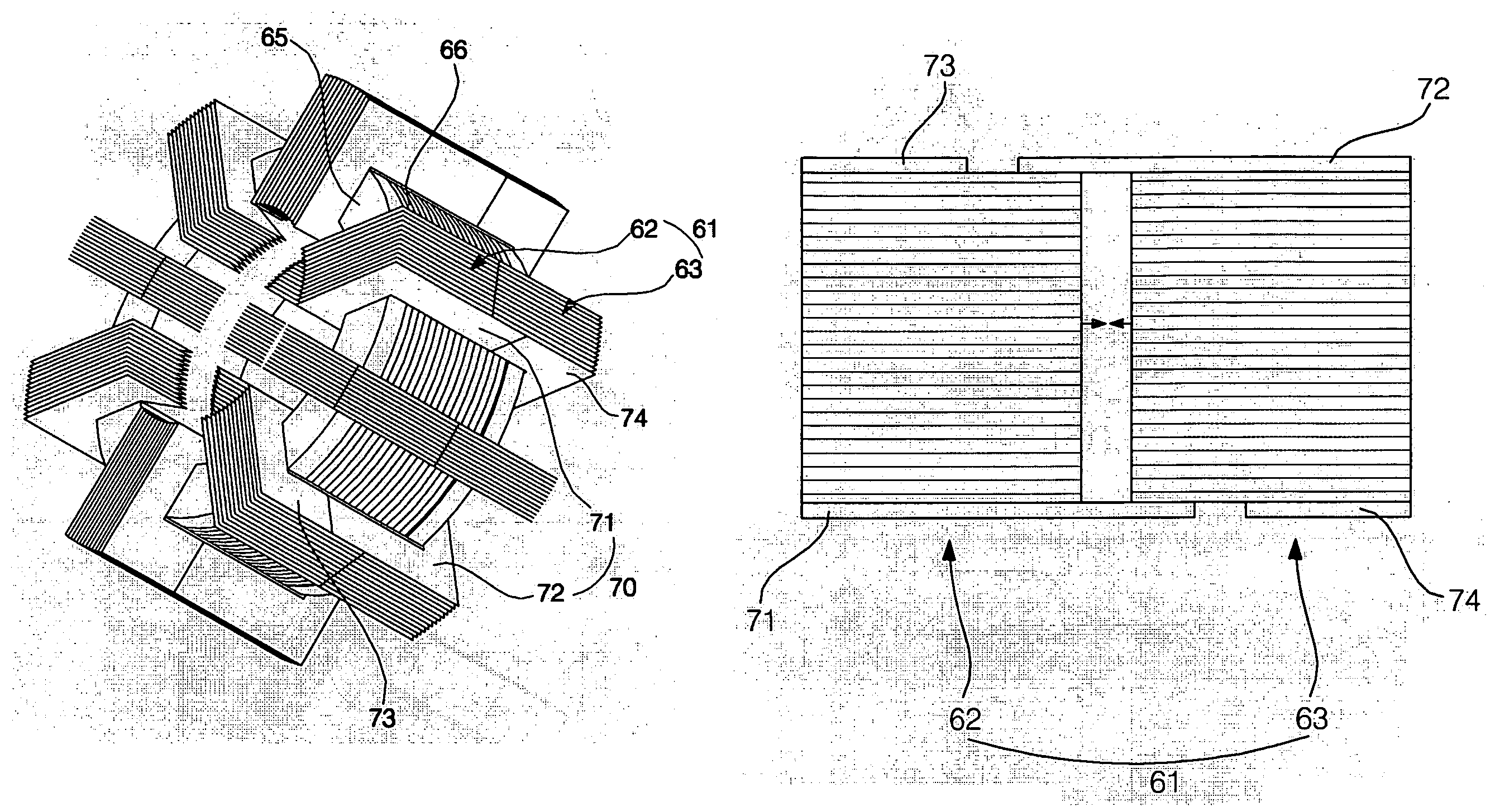
[0042]FIG. 4 is a longitudinal sectional view illustrating a linear compressor with a linear motor according to the present invention mounted therein, FIG. 5 is an enlarged perspective view illustrating outer cores according to the present invention, which are assembled to a bobbin, FIG. 6 is a front view illustrating an outer core according to the present invention, and FIG. 7 is a plan view of the outer core seen from the direction indicated by the arrow A in FIG. 6.

[0043]Referring to FIG. 4, the linear compressor with the liner motor according to the present invention mounted therein comprises: a shell 50; and a linear compression unit 51 disposed in the shell 50 for compressing fluid.

[0044]The linear compression unit 51 comprises: a cylinder block 53 having a cylinder 52; a back cover 55 having a fluid inlet port 54; a piston 56 disposed such that th...


PUM


Abstract

Disclosed herein is an outer core assembly structure of a linear motor. At least one of a plurality of core sheets is an extended core sheet having a length greater than that of the other core sheets. Consequently, easy and convenient alignment of first and second outer core blocks is accomplished when the first and second outer core blocks are assembled, and the first and second outer core blocks are securely fixed to each other. Furthermore, an additional reinforcing cover is not necessary. Consequently, assembly of the first and second outer core blocks is easily and conveniently accomplished, and therefore, the assembly costs are reduced.

Description

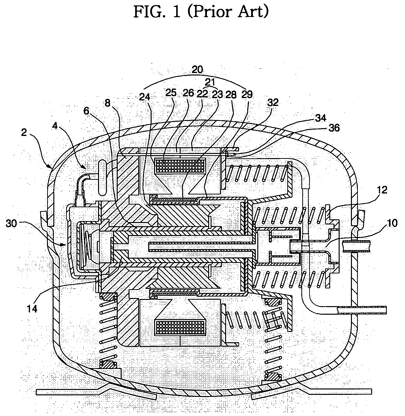
BACKGROUND OF THE INVENTION[0001]1. Field of the Invention[0002]The present invention relates to a linear motor, and, more particularly, to an outer core assembly structure of a linear motor wherein at least one of a plurality of core sheets is an extended core sheet having a length greater than that of the other core sheets, whereby easy and convenient alignment of first and second outer core blocks is accomplished when the first and second outer core blocks are assembled, and therefore, the first and second outer core blocks are securely fixed to each other.[0003]2. Description of the Related Art[0004]Generally, a linear compressor is an apparatus that introduces, compresses, and discharges refrigerant gas (hereinafter, referred to as “fluid”) through a linear reciprocating movement of a piston in a cylinder, which is performed by a linear driving force of a linear motor.[0005]FIG. 1 is a longitudinal sectional view illustrating a linear compressor with a conventional linear motor...

Claims


Application Information

Patent Timeline
Patent Type & Authority Patents(United States)
IPC IPC(8): H02K1/14H02K33/00H02K33/16
CPCF04B35/045H02K33/16H02K1/145F04B39/14F04B39/121F05B2210/12F05B2210/14F05B2260/60Y10S417/902
Inventor KIM, JIN DONG
Owner LG ELECTRONICS INC
Learn More