
Abnormality detection apparatus for exhaust gas purification apparatus for internal combustion engine

a technology of exhaust gas purification apparatus and abnormality detection, which is applied in the direction of fluid tightness measurement, combination devices, and dispersed particle filtration, etc., can solve the problems of unbalanced pulsations reaching the differential pressure sensor, and influence of pressure pulsation in the detection value of pressure differen

Active Publication Date: 2008-07-08
DENSO CORP
View PDF11 Cites 19 Cited by
  • Summary
  • Abstract
  • Description
  • Claims
  • Application Information

AI Technical Summary

Benefits of technology

The invention is an abnormality detection apparatus for an exhaust gas purification apparatus for an internal combustion engine. The apparatus is designed to easily detect abnormalities in the pressure difference of the particulate filter caused by breakage of the piping connecting the filter. The apparatus measures the pulsation of the pressure difference and compares it to a reference value to determine if there is an abnormality. By measuring the pulsation and detecting it in this way, the apparatus can accurately detect abnormalities in the piping without the need for direct inspection. The apparatus can also be set up to detect abnormalities in the downstream piping, which has been difficult to do in the past. The invention is effective in detecting small abnormalities and can be easily integrated into existing exhaust gas purification apparatus.

Problems solved by technology

When any breakage, or the like, exists in the piping, on the other hand, the magnitudes of the pressure pulsations reaching the differential pressure sensor become unbalanced between the two paths and the influences of the pressure pulsation greatly appear in the detection value of the pressure difference.

Method used


Image

  • Abnormality detection apparatus for exhaust gas purification apparatus for internal combustion engine
  • Abnormality detection apparatus for exhaust gas purification apparatus for internal combustion engine
  • Abnormality detection apparatus for exhaust gas purification apparatus for internal combustion engine

Examples


Embodiment Construction

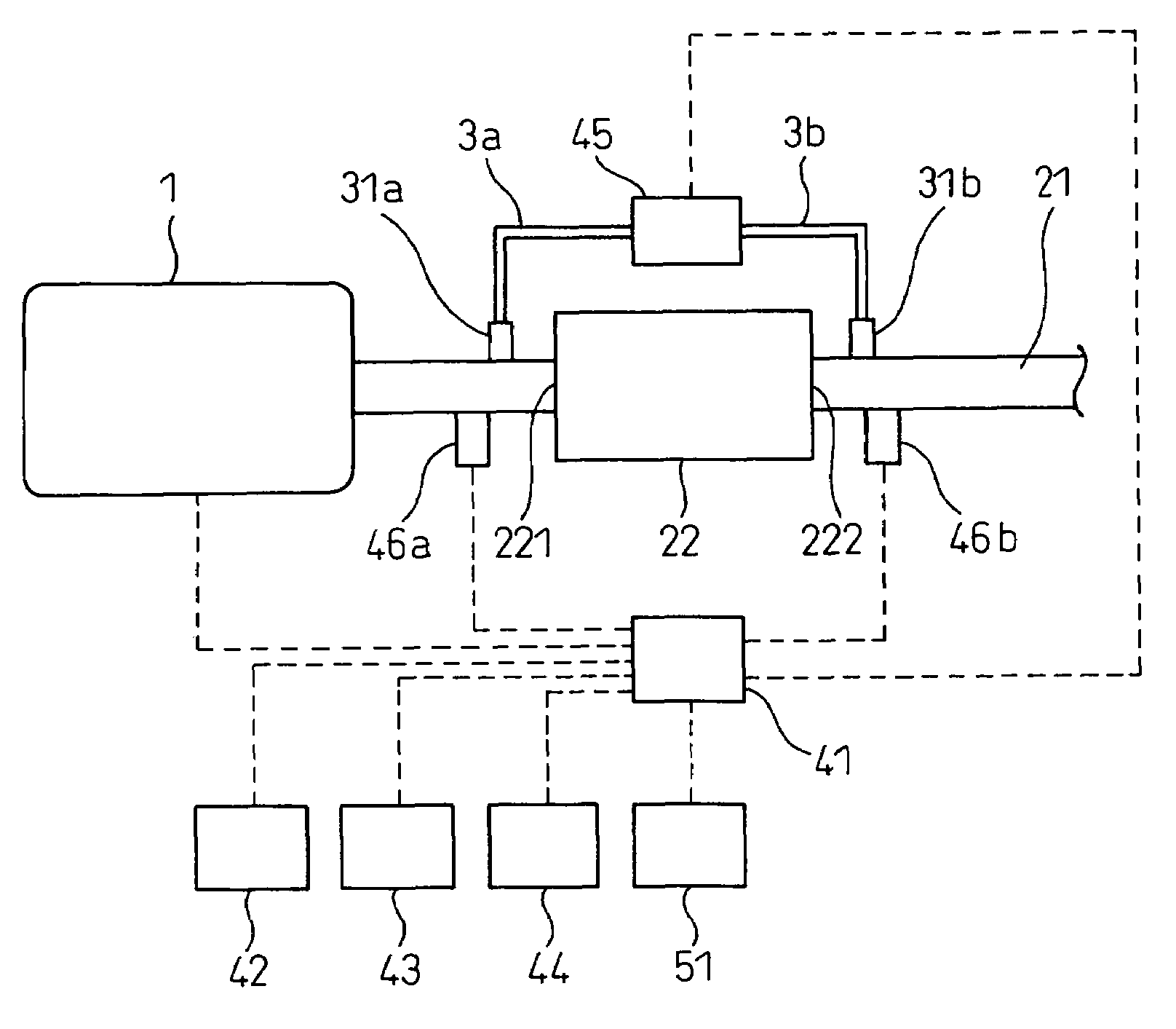
[0031]FIG. 1 shows a Diesel engine having an exhaust gas purification apparatus according to a first embodiment of the invention. An engine main body 1 includes multi-cylinder. An air-fuel mixture is serially burnt inside the cylinders and turning power is outputted from a crank shaft, not shown in the drawing. The following explanation will be given on the case where the engine main body 1 has 4 cylinders. The exhaust gas emitted from each cylinder after combustion of the air-fuel mixture in each cylinder is purified by the apparatus arranged in an exhaust passage 21. A particulate filter (hereinafter called “DPF (Diesel Particulate Filter)” from time to time) 22 is arranged as one of such apparatuses.

[0032]The DPF 22 is produced by shaping heat-resistant ceramics such as cordierite into a honeycomb structure and is sealed in such a fashion that a large number of cells as the gas passages alternately form inlets 221 and outlets 222 at both ends of the DPF 22. An oxide catalyst such...


PUM

PropertyMeasurementUnit
crank angleaaaaaaaaaa
inlet pressureaaaaaaaaaa

Abstract

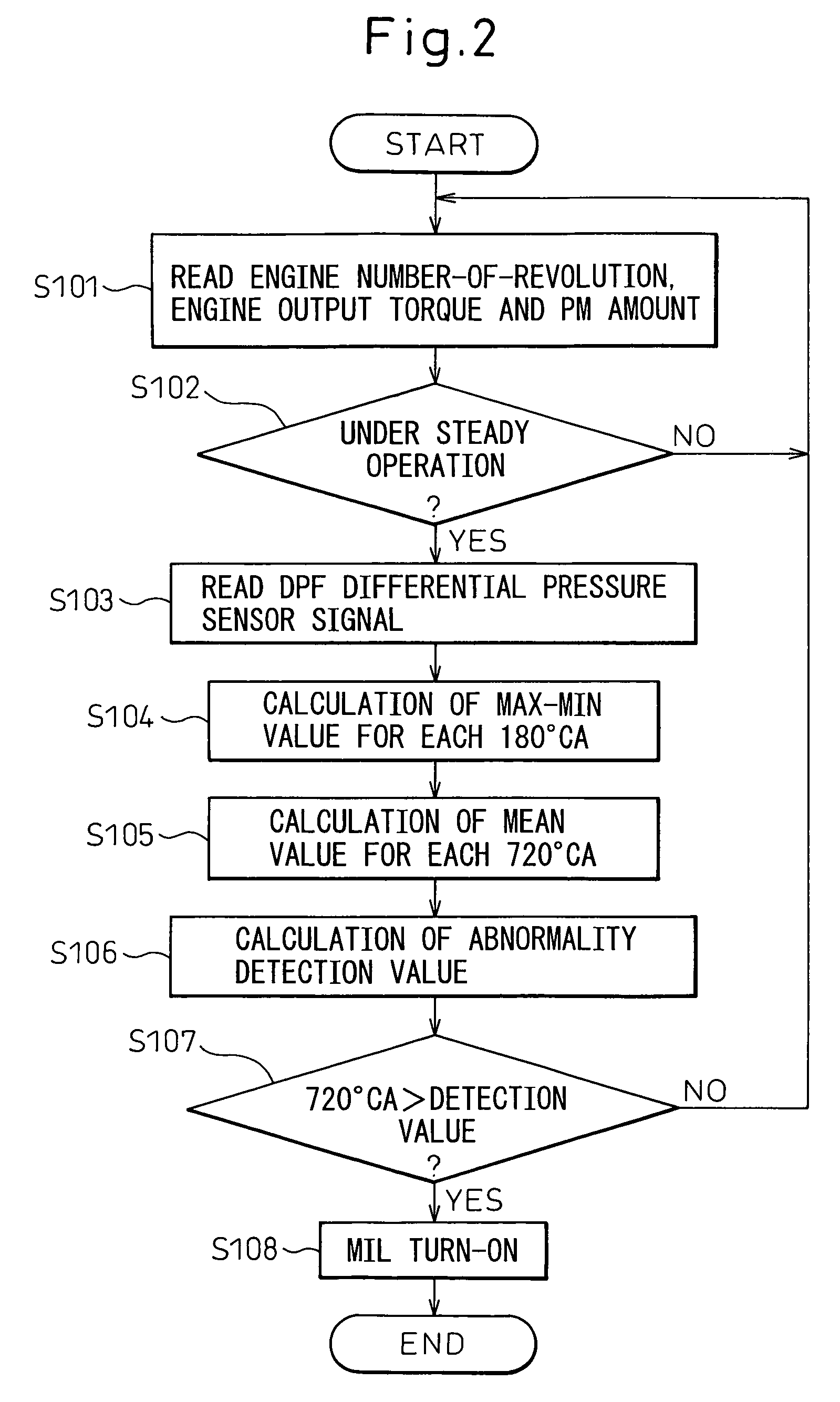
Unless an abnormality exists in piping introducing a pressure from front and rear of DPF 22 into a differential pressure sensor 45, pulsations of pressure propagation through an exhaust passage 21 is offset in a detection value of a pressure difference of the differential pressure sensor 45, and an amplitude of the detection value of the DPF pressure difference resulting from pulsation of the pressure becomes small. If a crack exists in one of the piping 3a and 3b, the influence of a pulsation of the pressure appears in the DPF pressure difference and the amplitude of the detection value of the DPF pressure difference becomes large. The amplitude of the detection value of the DPF pressure difference is compared with the reference value and is detected as being abnormal when it is large, utilizing the phenomenon described above.

Description

BACKGROUND OF THE INVENTION[0001]1. Field of the Invention[0002]This invention relates to an exhaust gas purification apparatus, having a particulate filter, for an internal combustion engine. More particularly, the invention relates to an abnormality detection apparatus for detecting an abnormality in an exhaust gas purification apparatus for an internal combustion engine.[0003]2. Description of the Related Art[0004]Reduction of exhaust gas emission has been required in recent years for internal combustion engines mounted in automobiles and so forth. In a compression ignition type Diesel engine using light oil as fuel, in particular, removal of particulate matters such as soot and SOF (soluble organic fraction) in the exhaust gas has been necessary in addition to removal of CO, HC and NOx. Therefore, it has been customary to arrange a particulate filter in an exhaust passage and to trap particulate matters in the exhaust gas.[0005]The particulate filter allows the passage of an inf...

Claims


Application Information

Patent Timeline
Patent Type & Authority Patents(United States)
IPC IPC(8): B01D46/00B01D46/46F01N3/021F01N3/02F01N3/18F01N11/00
CPCB01D46/2418B01D46/46B01D46/446B01D2279/30Y10S55/10Y10S55/30
Inventor KARIYA, YASUHIROKUBOSHIMA, TSUKASA
Owner DENSO CORP
Learn More