
Apparatus and method for generating harmonics in an audio signal

Inactive Publication Date: 2008-07-01
PANASONIC INTELLECTUAL PROPERTY CORP OF AMERICA
View PDF10 Cites 19 Cited by
  • Summary
  • Abstract
  • Description
  • Claims
  • Application Information

AI Technical Summary

Benefits of technology

[0029]An object of the present invention is to provide an audio-signal-processing apparatus that can suppress sound quality degradation in a complex tone and a method thereof.
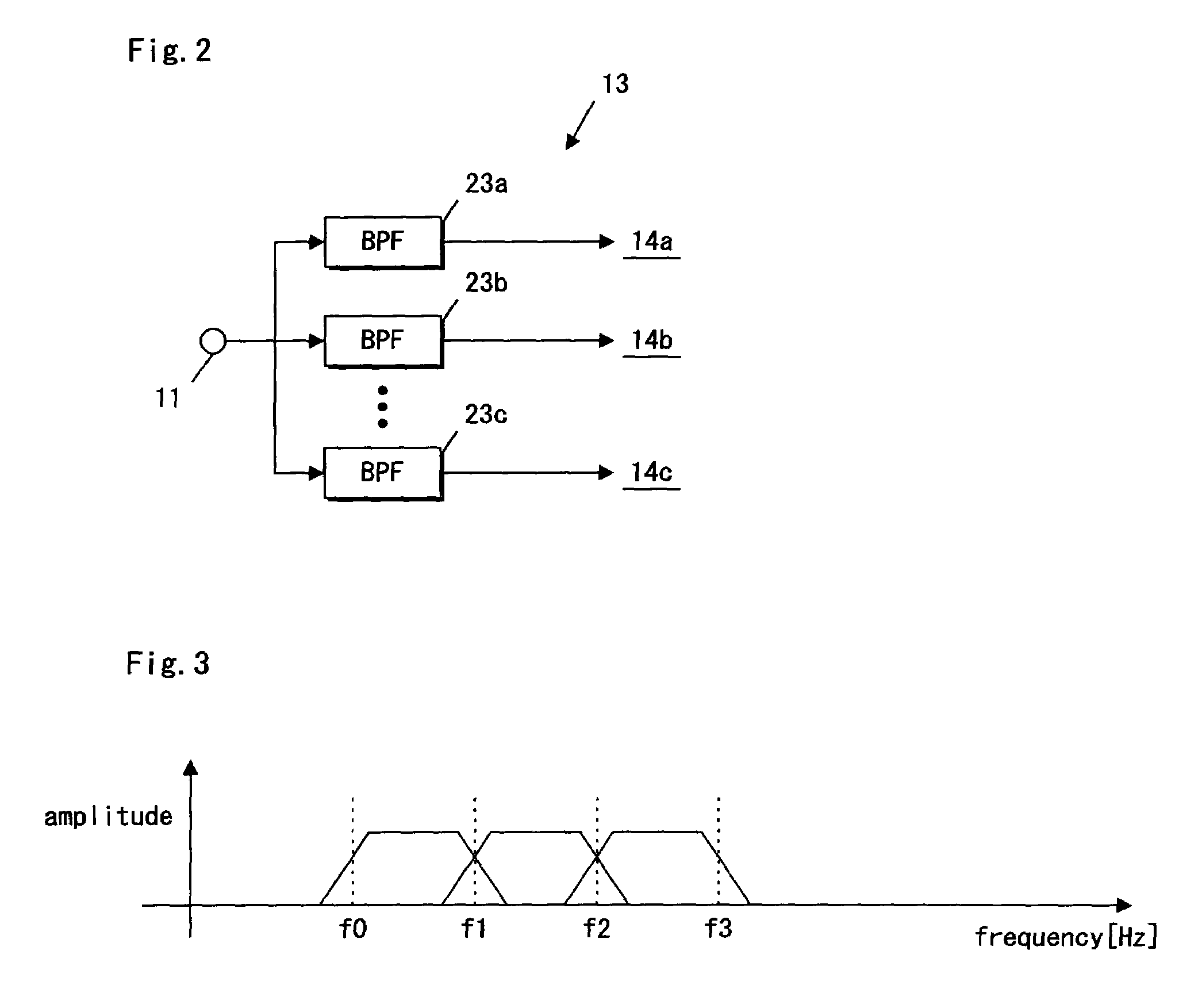
[0031]Since the band-decomposition unit decomposes the low frequency component into a plurality of narrow frequency bandwidths, the fundamental tone and the harmonic-tones thereof that belong to a same band are suppressed There fore, the distortion can be restrained and sound quality can be improved.
[0032]A second aspect of the present invention provides an audio-signal-processing apparatus as defined in the first aspect of the present invention, wherein the band-decomposition unit is operable to decompose the low frequency component of the input-audio-signals such that each of a fundamental tone and harmonic-tones of the fundamental tone belong to a different frequency band. With this structure, the fundamental tone and the harmonic-tones thereof do not belong to a same band, thereby the distortion can be restrained and sound quality can be improved.
[0034]A fourth aspect of the present invention provides an audio-signal-processing apparatus as defined in the first aspect of the present invention, wherein the decomposition characteristic is defined based on a low interval limit. With this structure, the decomposition characteristic for band-decomposition can be optimized, and the circuit scale can be reduced.

Problems solved by technology

However, this full-wave-rectification system poses a problem in that odd harmonic-tones cannot be generated.
Additionally, problems encountered when using other harmonic-series-generating methods, such as the full-wave-rectification method and the power methods, will be described.
However, although the second harmonic components are generated in either case, some distortions occurs due to the inclusion of other components than the second harmonic components (e.g., the fundamental frequency equal to the highest common factor of the fundamental frequency of two pure tone components).
As a result, the processed signal waveform is not similar to the original signal and waveform distortion occurs.

Method used


Image

  • Apparatus and method for generating harmonics in an audio signal
  • Apparatus and method for generating harmonics in an audio signal
  • Apparatus and method for generating harmonics in an audio signal

Examples


Embodiment Construction

[0055]Preferred embodiments of the present invention are now described in conjunction with the accompanying drawings. FIG. 1 (a) is a block diagram illustrating an audio-signal-processing apparatus according to an embodiment of the present embodiment. An input terminal 11, illustrated in FIG. 1, inputs an input-audio-signal. A band-decomposition unit 13 has a decomposition characteristic, and it decomposes the low frequency components of the input-audio-signal into a plurality of frequency components that have different frequency bands based on the decomposition characteristic.

[0056]A plurality of harmonic-series-generating units 14a-14c generate harmonic-tone components for each band signal decomposed by the band-decomposition unit 13. As a harmonic-series-generating method, any harmonic-tone-component method previously described (e.g. the full-wave-rectification method, the power method, the zerocrossing method, etc.) can be used.

[0057]However, the numbers and amplitude levels of ...


PUM


Abstract

An audio-signal-processing apparatus includes a band-decomposition unit utilizing a band-decomposition characteristic based on the harmonic-tone composition of musical instruments. A low interval limit generates the harmonic-tone to each band signal after decomposing the bass signal into a plurality of band signals. The audio-signal processing apparatus generates a harmonic-tone individually for each pure tone component, which includes complex tones and suppresses deterioration of the sound quality.

Description

BACKGROUND OF THE INVENTION[0001]1. Field of the Invention[0002]This invention relates to an audio-signal-processing apparatus capable of harmonic-series-generation and a method thereof.[0003]2. Description of the Related Art[0004]Audio-signal-processing apparatuses with harmonic-series-generation have been proposed for various purposes. Generally known is, for example, an effector apparatus that gives variations to tone color of a musical instrument and voice, especially, a virtual reproduction system of bass sound that generates a harmonic-tone for a bass component to reinforce the bass sounds in a small speaker.[0005]A prior art virtual reproduction system of bass sound will be described with reference to FIG. 9 through FIG. 13. FIGS. 9 (a) and (b) are block diagrams illustrating a conventional audio-signal-processing apparatus. Each harmonic-tone can be generated with a full-wave-rectification method, a power method, a zerocrossing method or other similar method.[0006]A first ex...

Claims


Application Information

Patent Timeline
IPC IPC(8): H03G5/00G10H1/00H04R3/00G10H1/06G10H1/12G10H1/16H03G5/10H03G5/16
CPCG10H1/0091G10H1/06H04S1/002H03G5/10H04R3/04G10H1/125
Inventor KATOU, NAOYUKIKUMAMOTO, YOSHINORIIKEDA, JUN
Owner PANASONIC INTELLECTUAL PROPERTY CORP OF AMERICA
Learn More