Time keeping system with automatic daylight savings time adjustment
a time keeping system and automatic technology, applied in the field of time keeping systems, can solve the problems of adding cost to the time keeping system, restricting the areas or locations in which the time keeping system may operate, etc., and achieve the effect of reducing the time differen
- Summary
- Abstract
- Description
- Claims
- Application Information
AI Technical Summary
Benefits of technology
Problems solved by technology
Method used
Image
Examples
first embodiment
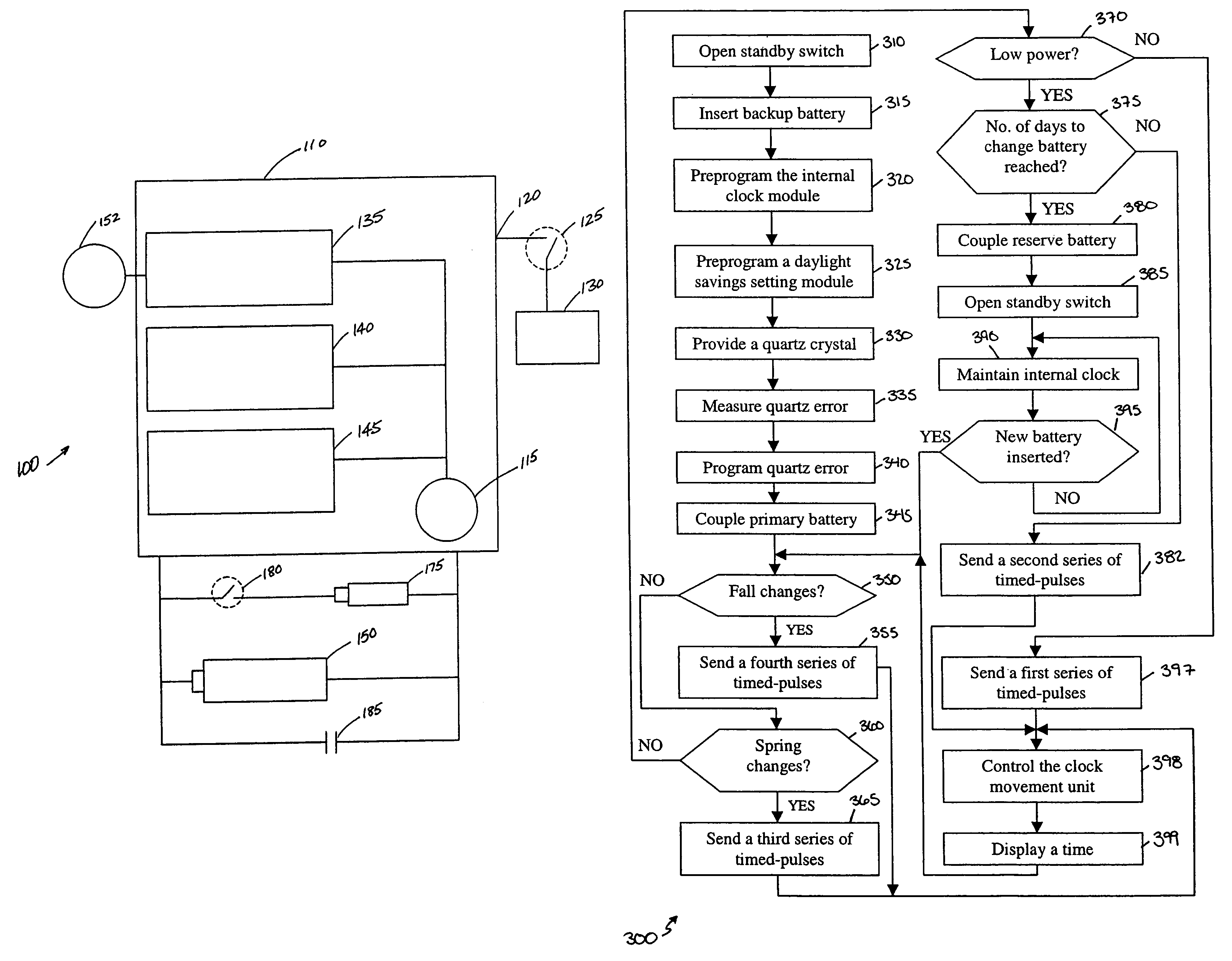
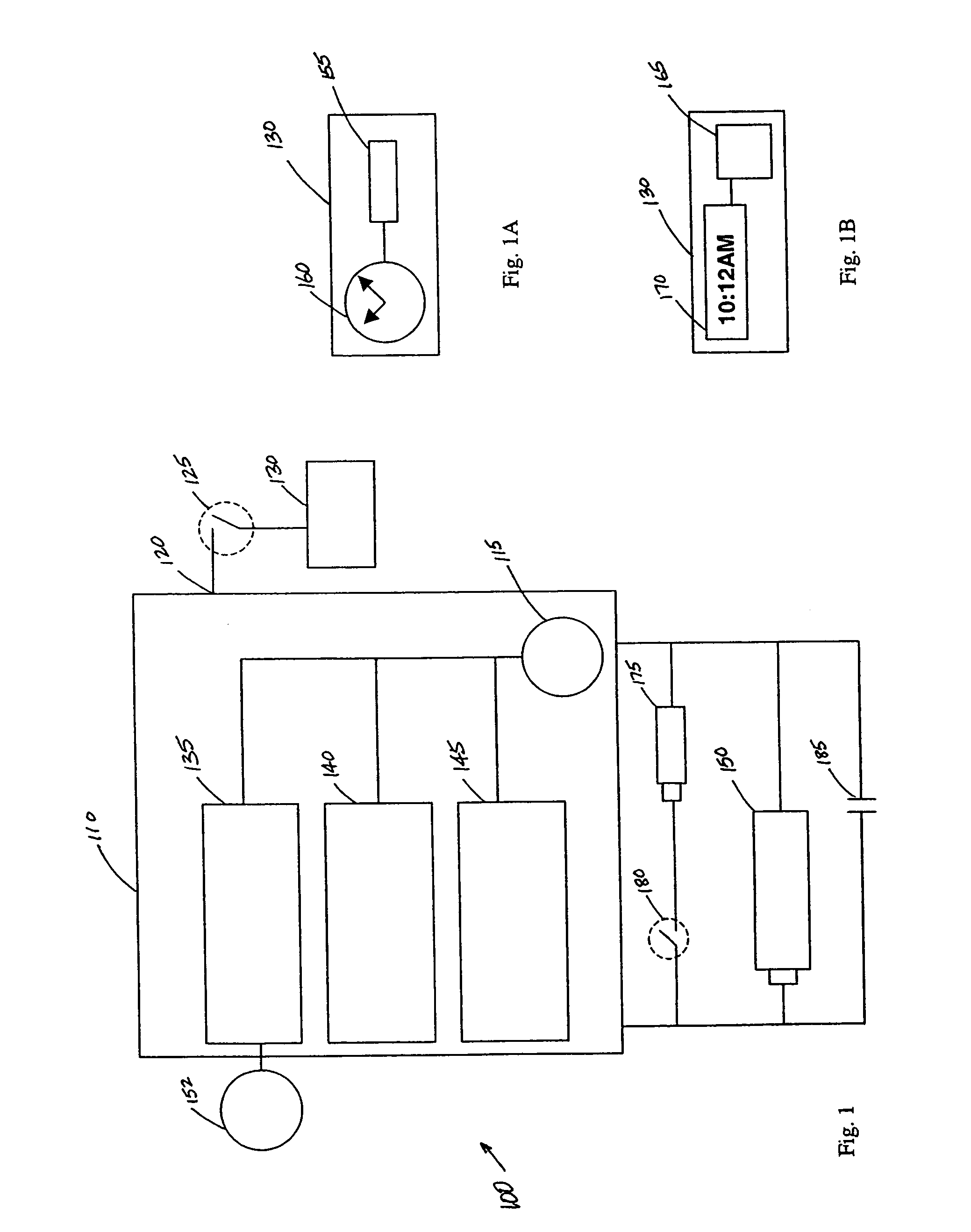
[0023]FIG. 1 illustrates the functionality of a daylight savings time clock system 100 in accordance with the present invention. The daylight savings time clock system 100 includes a processor 110, which receives programming information through a programming pad 115 and sends a series of timed-pulses from a driver output 120 through a standby switch 125 to a clock movement unit 130. The processor 110 further includes a preprogrammed internal clock module 135, a preprogrammed daylight savings time setting module 140, and a low power detection module 145. The preprogrammed internal clock module 135 and the preprogrammed daylight savings time setting module 140 are programmed with time information and daylight savings changes through the programming pad 115 during the manufacturing process. These changes preferably include dates and times for daylight savings changes and a calendar that includes a number of days in leap years, non-leap years, and millennium leap years. The low power de...
second embodiment
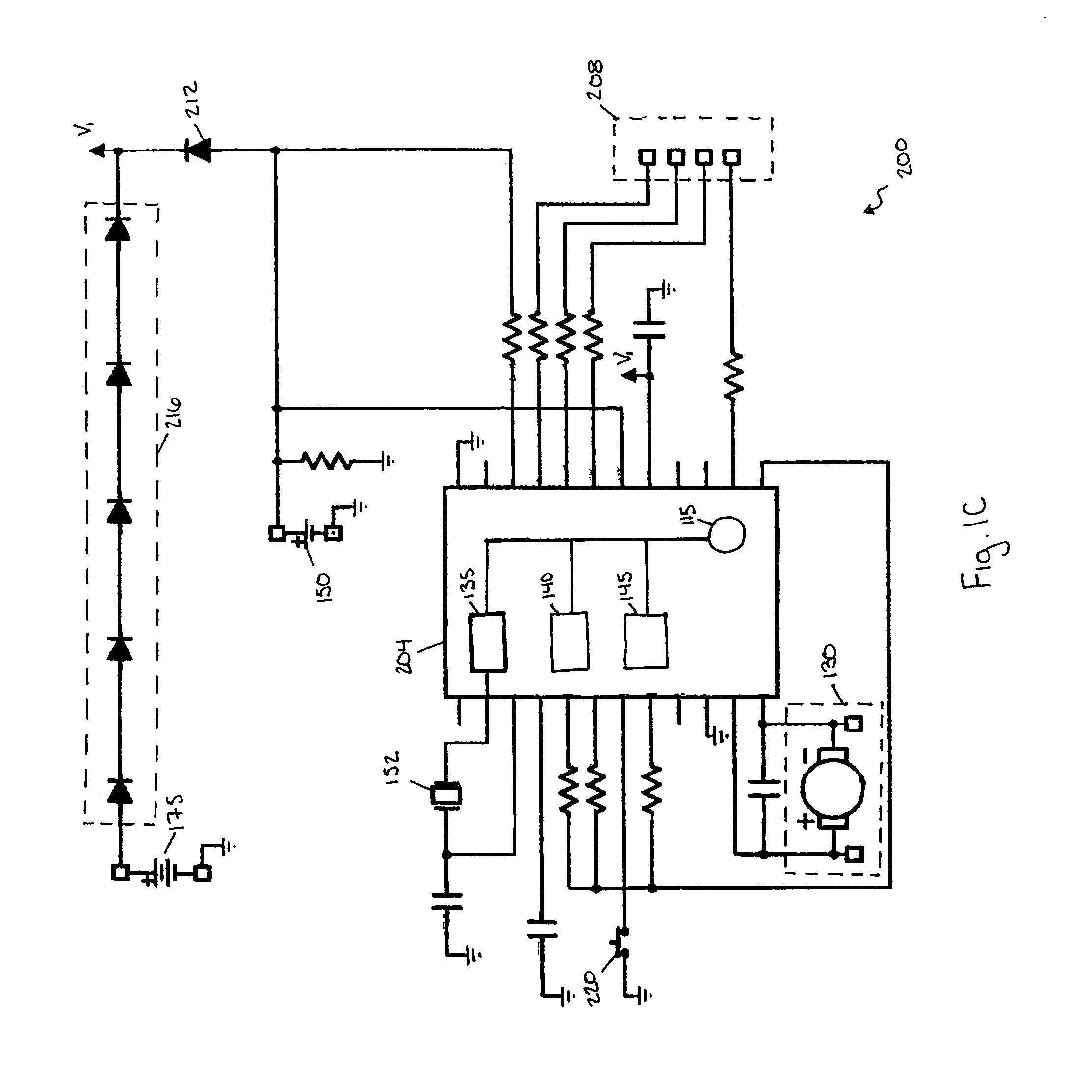
[0025]In the present invention illustrated in FIG. 1C, a daylight savings time keeping system 200 includes a processor 204. The processor 204 includes the same modules and features included in the processor 110. However, the processor 204 also monitors the voltage of the primary battery 150 and, then, automatically performs the functions of the switches 180 and 125 in the event of low power detection or insertion of a new primary battery. When the processor 204 detects a low voltage output from the primary battery 150, the processor 204 disconnects the primary battery 150 and switches to the reserve power source or backup battery 175. Once the system 200 is being powered by the backup battery 175, the processor 204 deactivates the clock movement unit 130 to preserve the backup battery 175. The processor 204 does not re-activate the clock movement unit 130 until a new primary battery 150 is inserted and the processor does not detect a low voltage output from the new primary battery 1...
third embodiment
[0034]A time keeping system 400 of the present invention and having multiple operational modes is illustrated in FIG. 3. The time keeping system 400 generally includes a clock movement unit 405, a processor or controller 410, a frequency generating unit 415, a primary power source 420, and a secondary power source 425. In one embodiment, the system 400 has a majority of its components residing in a conventional or standard compartment or gearbox, (e.g., a clockwork having the dimensions of 2 inches by 2 inches by ⅝ inches).
[0035]The clock movement unit 405 controls a display module (not shown). The movement unit 405 provides the mechanics or electronics necessary to advance or change a time being displayed by the display module (not shown) in response to timing signals or reference pulses generated by the controller 410. In one embodiment, the clock movement unit 405 is a clock motor, such as a bi-polar stepping motor, for advancing or changing an analog display (not shown). In anot...
PUM
 Abstract
Description
Claims
Application Information
 - R&D
- Intellectual Property
- Life Sciences
- Materials
- Tech Scout
- Unparalleled Data Quality
- Higher Quality Content
- 60% Fewer Hallucinations
Browse by: Latest US Patents, China's latest patents, Technical Efficacy Thesaurus, Application Domain, Technology Topic, Popular Technical Reports.
© 2025 PatSnap. All rights reserved.Legal|Privacy policy|Modern Slavery Act Transparency Statement|Sitemap|About US| Contact US: help@patsnap.com


