
Engine system and method

a technology of control system and engine, which is applied in the direction of electric control, fuel injection control, machines/engines, etc., can solve the problems of reducing fuel efficiency and emissions, and degrading combustion

Active Publication Date: 2016-11-03
GE GLOBAL SOURCING LLC
View PDF2 Cites 6 Cited by
  • Summary
  • Abstract
  • Description
  • Claims
  • Application Information

AI Technical Summary

Benefits of technology

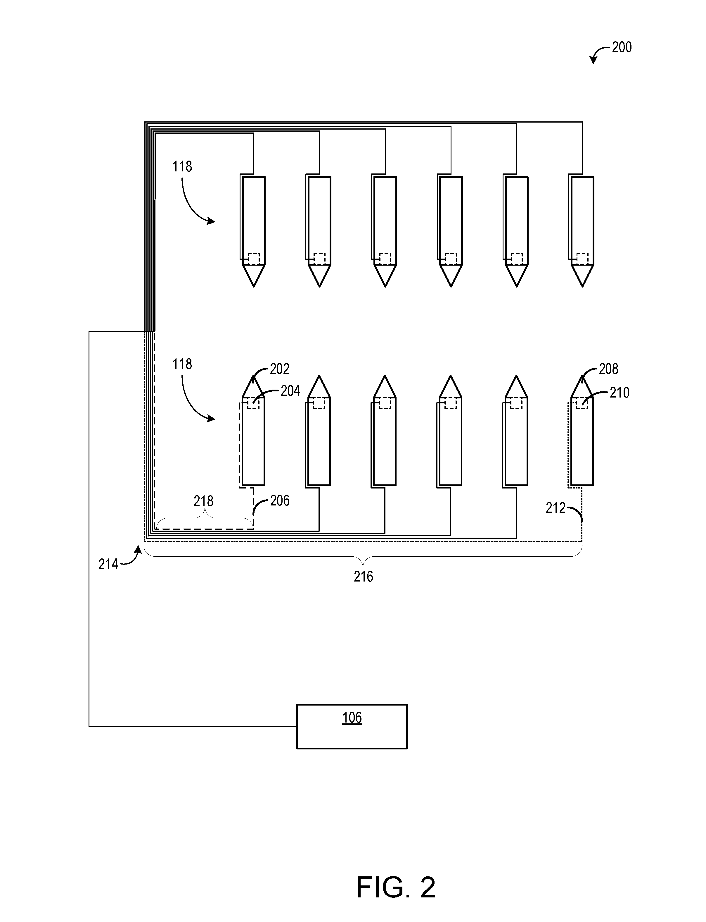
The patent describes a control system for fuel injectors that allows for precise control of fuel injection timing and event duration. The system adjusts the actuation signal of the fuel injector by adjusting the rate of current rise to track a reference current rise. This ensures that the current at the solenoid remains at a reference level, regardless of changes in impedance. Moreover, the system allows for individual control of fuel injectors and injector drive circuits to maintain a consistent current waveform and mitigate timing differences among fuel injectors. Additionally, the system uses an averaging filter to reduce electromagnetic interference.

Problems solved by technology

This may result in differing start of injection times among cylinders, degrading combustion and potentially reducing fuel efficiency and emissions.

Method used


Image

  • Engine system and method
  • Engine system and method
  • Engine system and method

Examples


Embodiment Construction

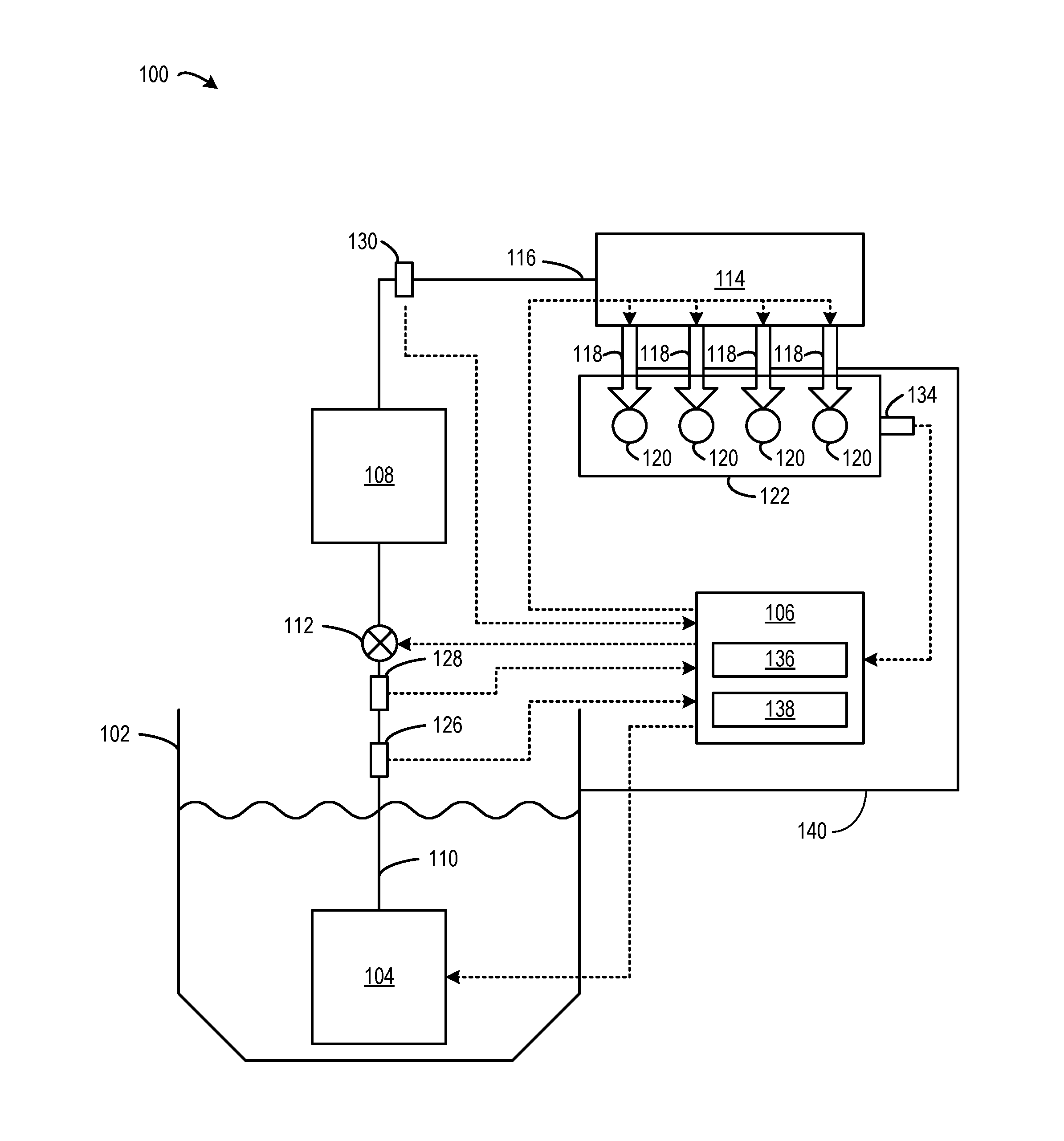
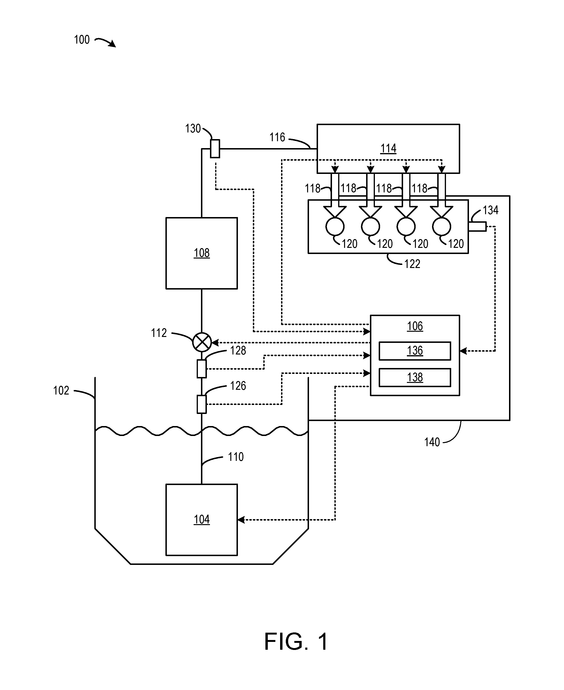
[0015]The following description relates to various embodiments of controlling an actuation signal to switch an actuator from a first position to a second position. The actuator may be a suitable actuator that may benefit from tightly-controlled timing of the actuation switch, such as engine system actuators including a fuel injector, spark plug, intake or exhaust system valve, or other actuator. Additionally, the actuation signal may be controlled so that the actuator switches from the first position to the second position at an equivalent time that a second actuator switches from a first position to a second position. For example, two fuel injectors may be controlled to both open at the same time in respective cylinder cycles. To control the actuation signal, the current supplied to each actuator may be monitored and an average voltage supplied to each actuator may be adjusted such that the monitored current for each actuator tracks a reference current waveform. The reference curre...


PUM


Abstract

Various methods and systems are provided for controlling and shaping the current waveform for a solenoid in a fuel injector that has variable impedance.

Description

CROSS REFERENCE TO RELATED APPLICATIONS[0001]This application claims priority to U.S. Provisional Application No. 62 / 154,476, filed Apr. 29, 2015, which is hereby incorporated in its entirety herein by reference for all purposes.BACKGROUND[0002]1. Technical Field[0003]Embodiments of the subject matter disclosed herein relate to methods and systems for control systems for fuel injectors in an engine.[0004]2. Discussion of Art[0005]In some vehicles, fuel is provided to an engine by a common rail fuel system. In the common fuel rail system, fuel injectors inject fuel from the common fuel rail to cylinders of the engine for combustion. The injectors open via actuation from a solenoid valve controlled by a controller. To initiate injection of a given injector, the controller sends a signal to activate the solenoid valve of that injector, resulting in a voltage source being applied to the solenoid. Once the current in the solenoid reaches a threshold, the valve opens and injection begins....

Claims


Application Information

Patent Timeline
Patent Type & Authority Applications(United States)
IPC IPC(8): F02D41/30F02D41/20
CPCF02D41/3005F02D2041/2017F02D41/20F02D2041/2027F02D2041/2034F02D2041/2051F02D2041/2058
Inventor SHEN, NINGFERGUSON, MATTHEW K.TRAVAGLINI, DOMINICK
Owner GE GLOBAL SOURCING LLC
Learn More