Device at handtruck

a hand-held and hand-held technology, applied in the direction of steering controls, hand carts, levers, etc., can solve the problems of difficult to overcome, couple of millimeters can constitute a difficult obstacle, become very tiring, etc., to achieve easy to understand and handle, transfer large forces, and little space

Active Publication Date: 2008-07-01
BT INDS
View PDF8 Cites 5 Cited by
  • Summary
  • Abstract
  • Description
  • Claims
  • Application Information

AI Technical Summary

Benefits of technology

[0010]In the handle of the tiller a control is arranged for the choice of drive aid rearward backward and free respectively, which control may be designed to cooperate with or be integrated with the control for lifting and lowering of the load so that one does not by mistake try to execute several each other counteracting measures at the same time. The control may for instance have a similar design as the speed control of a truck. In this way the function becomes easy to understand and handle and one does not have to learn different hand grips for different trucks. The control may either be so arranged that it remains in the set position or with a return springing to the free or neutral position.
[0011]The switchable coupling between crank and each wheel comprise advantageously an inner cylinder surface connected with the crank and provided with one or several flat axial machined surfaces, which inner cylinder surface is surrounded by an outer herewith concentric cylinder surface that is connected with or integrated with the wheel. At the machined surfaces cylindrical axial rollers are arranged with a diameter that is larger than the distance between the cylinder surfaces but that are accommodated at the machined surfaces. Furthermore a holder is arranged for the rollers allowing a small circumferenceal movement for the rollers. By placing the holder so that the rollers are located in the middle of each machined surface the rollers will be entirely free and no force transfer can take place (neutral position). By displacing the holder in a first direction the rollers can at a relative movement of the cylinders be wedged between the machined surfaces in one direction, whereas movement in the opposite direction frees the rollers. If the holder is displaced in the opposite direction power transfer can take place in the opposite direction. Since the rollers take up little space and can transfer large forces the device becomes particularly compact and still very robust. Furthermore the possible steps become small and the drive free from play and silent. This lack of play contributes essentially to the precision in the maneuvering as well as to give the user a feel of reliability. The number of the rollers and machined surfaces can be chosen according to the torque that is to be transferred.

Problems solved by technology

Should however the lorry be standing inclined it may become very tiring.
Already a string of some or a couple of millimeters can constitute a difficult obstacle to pass even on otherwise even floors in stores, where trucks of this kind are frequently used.
In particular if the obstacle, however small, lies close to one of the truck wheels at starting this is difficult to overcome since the truck has no speed.
When the truck has gained a bit of speed the movement only has to be sustained and with the help of the speed obstacles can be passed that otherwise are impossible to overcome directly.
In particular for lighter users with consequently less available pulling force the above may be a serious problem and it is not always possible to back up and gain speed.

Method used


Image

  • Device at handtruck
  • Device at handtruck
  • Device at handtruck

Examples


Embodiment Construction

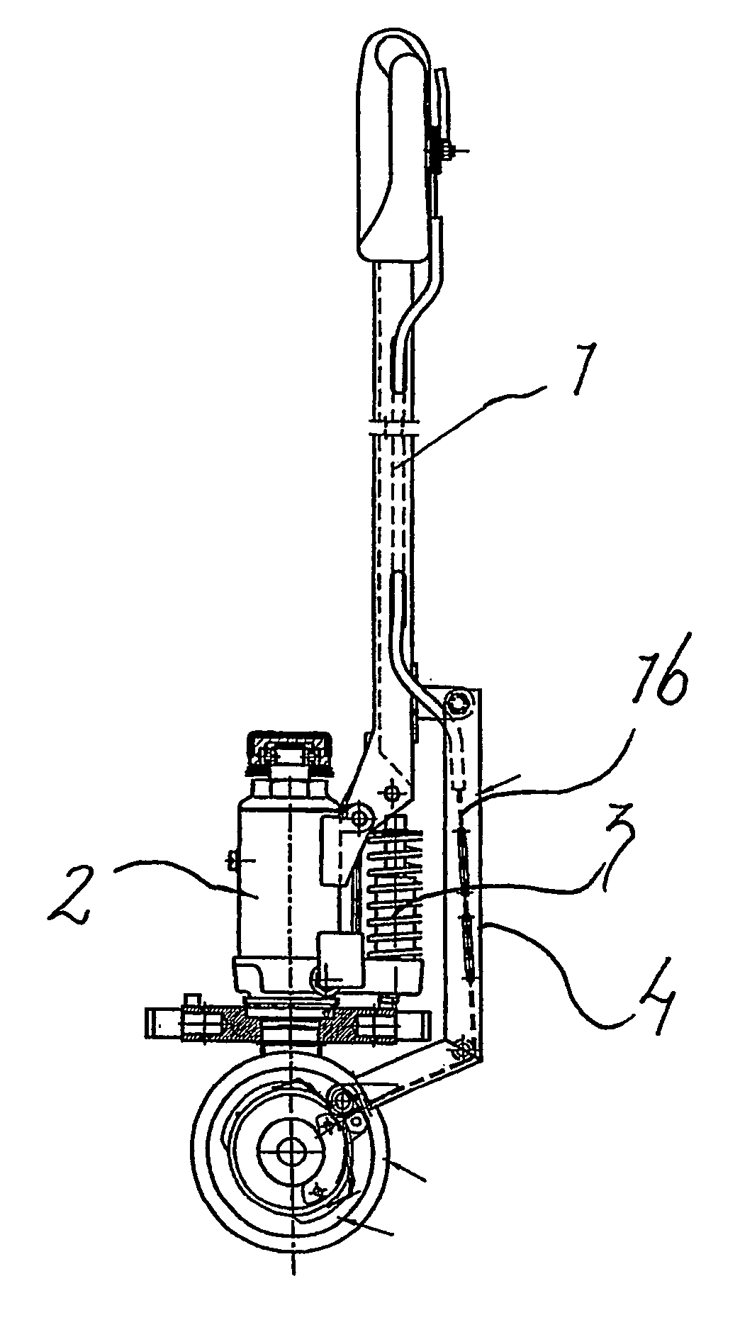
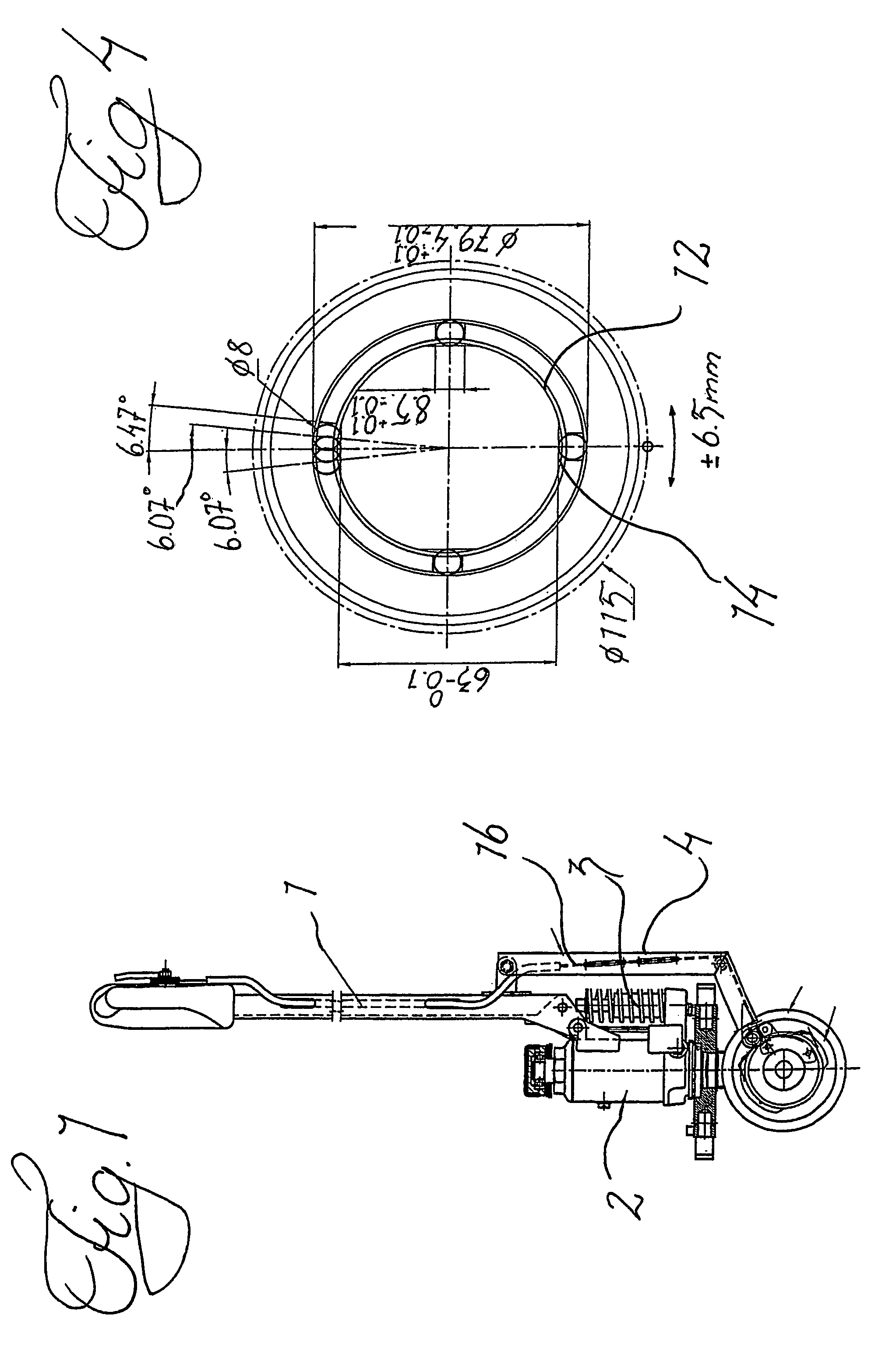
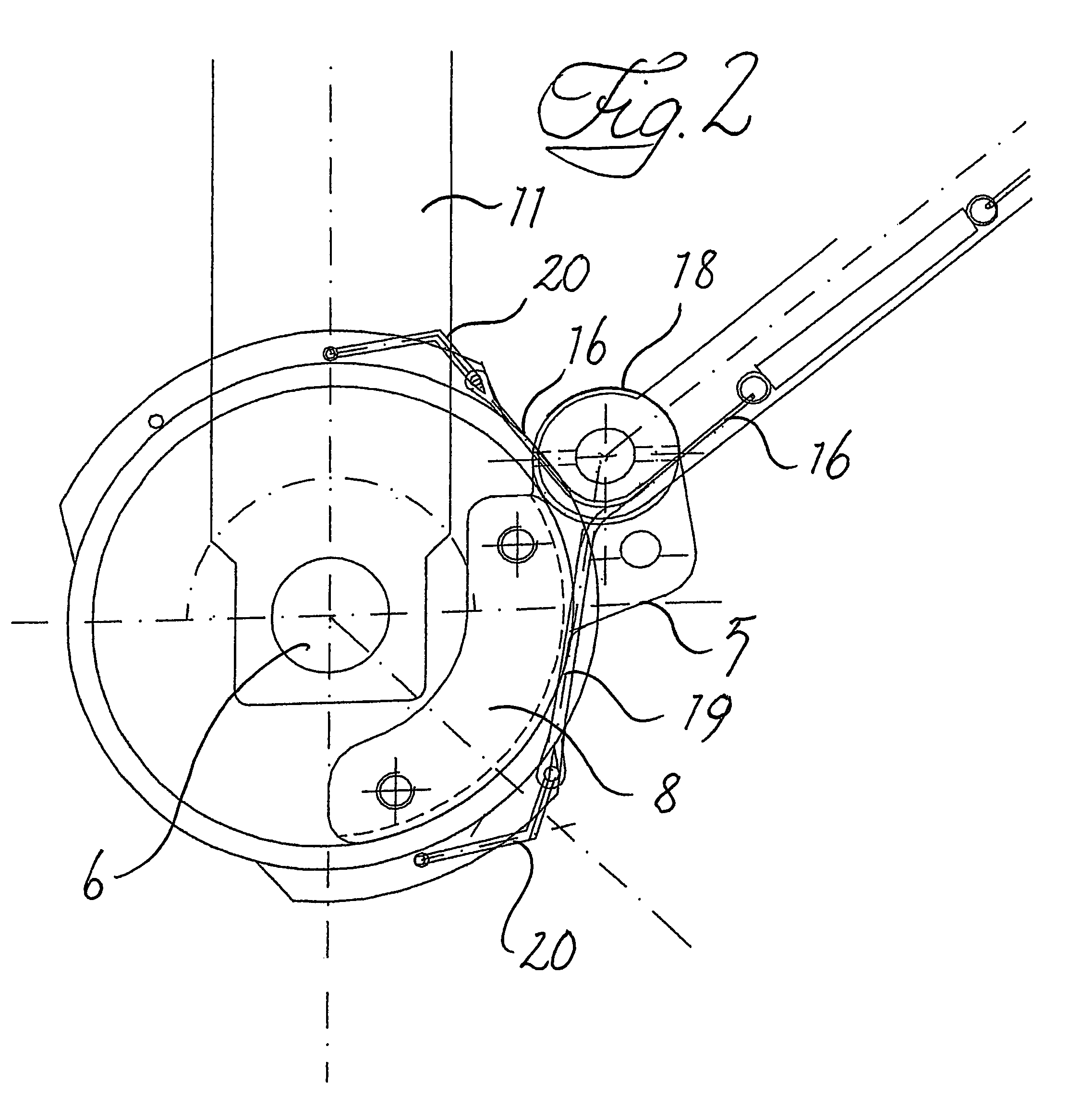
[0019]The handtruck partly shown in FIG. 1 includes a lifting part with forks, not shown, and a lifting cylinder 2 that via a pumping movement of the tiller 1 via the pumping cylinder 3 can be fed with oil so that the lifting part is lifted up from the steerable wheels, at the same time also rollers in the front end of the forks are, via a linkage, not shown, pressed down against the ground to achieve a lifting parallel to the ground. In the tiller 1 a short push / pull rod 4 is articulated extending down to a crank element 5 that via a slide or roller bearing, not shown, is journaled on the axle 6 of the two steerable wheels 7 of the truck.

[0020]The crank element 5 includes in its lower end an arched part 8 to which two circular elements 9 are bolted, which are journaled on the same axle as the wheels via slide bearings. Between the circular elements the axle 6 is fastened to the lower end of a rod 11 pivotable with the tiller 1. The circular elements are on their side facing the whe...


PUM


Abstract

Tiller truck provided with force transmitter in order to transmit a pumping movement with the tiller to the wheels via a coupling in order to facilitate the movement of the truck. The coupling is arranged so that it can be set for force transfer forward or rearward or in an entirely free position. A control for the control of the coupling is arranged in the tiller handle.

Description

BACKGROUND OF THE INVENTION[0001]At for instance loading of goods arranged on loading pallets, on and off lorries it is well known to use handtrucks that accompany the lorry. Lifting at these take place by a pumping with the tiller. Since these handtrucks are comparatively small and light the influence on the loading capacity of the truck as to weight and volume is very small. As long as the platform of the lorry or other floor is level and sufficiently even remarkably great loads can by hand be moved with a moderate effort. Should however the lorry be standing inclined it may become very tiring. The same thing is the case if the ground is uneven or if there is sand, small stones or other rubbish on the ground. Already a string of some or a couple of millimeters can constitute a difficult obstacle to pass even on otherwise even floors in stores, where trucks of this kind are frequently used. In particular if the obstacle, however small, lies close to one of the truck wheels at start...

Claims


Application Information

Patent Timeline
Patent Type & Authority Patents(United States)
IPC IPC(8): B62D51/04B62B3/06B62B5/00B62B5/06
CPCB62B3/0606B62B5/0026Y10T74/1579B62B5/063
Inventor JOHANSSON, RUNEERIKSSON, LARSGUSTAVSSON, JOAKIM
Owner BT INDS
Why Eureka
Try Eureka