
Driving support system and method

a technology of support system and support control, which is applied in the direction of anti-collision system, non-deflectable wheel steering, underwater vessels, etc., can solve the problems of significant discomfort of the driver, and achieve the effect of improving the performance of the support control and reducing discomfor

Inactive Publication Date: 2008-06-17
TOYOTA JIDOSHA KK
View PDF14 Cites 3 Cited by
  • Summary
  • Abstract
  • Description
  • Claims
  • Application Information

AI Technical Summary

Benefits of technology

The present invention provides a driving support system for vehicles that reduces discomfort for drivers during the driving support control. The system uses image data to determine the controlled variable of the actuator and limits the time change of the controlled variable when the driver's reaction to the support control is off the predetermined range. This limit value is set at the start of the driving support control to prevent discomfort during the initial stages of the control. The system also improves the performance of the driving support control in continuation by adjusting the limit value based on the driver's reaction to the support control. Overall, the system achieves both suppression of discomfort and improvement in the performance of the driving support control.

Problems solved by technology

In the conventional driving support systems, the steering reaction to steering of the steered wheels suddenly varies at the start or at the stop (end) of the driving support control, to cause the driver to sense significant discomfort.

Method used


Image

  • Driving support system and method
  • Driving support system and method
  • Driving support system and method

Examples


Embodiment Construction

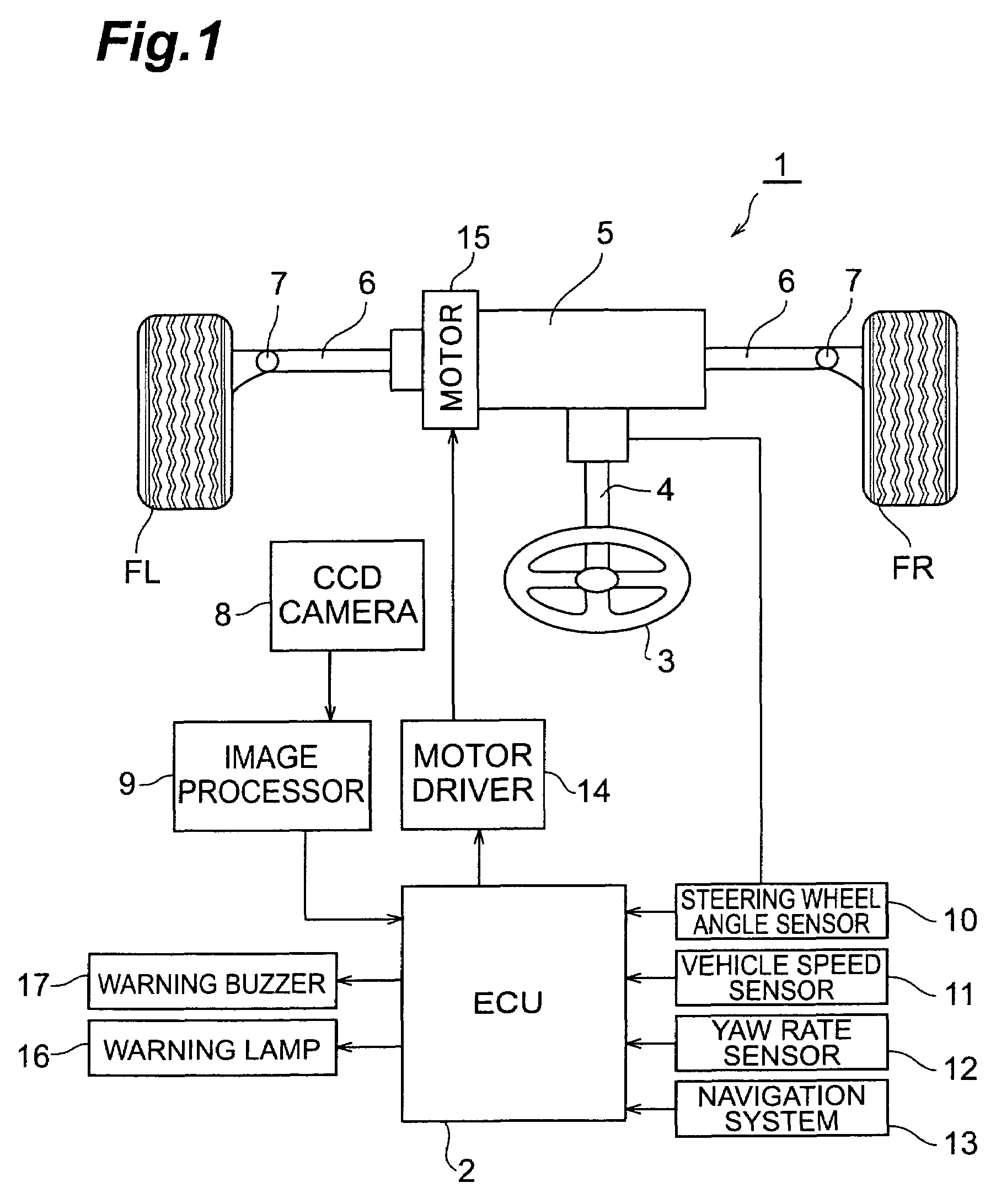
[0025]An embodiment of the driving support system according to the present invention will be described below. FIG. 1 shows a configuration diagram of vehicle 1 provided with the driving support system of the present embodiment. The vehicle 1 has an electronic control unit (ECU) 2, and ECU 2 controls a driving support (lane keep control). As shown in FIG. 1, the vehicle 1 has a steering wheel 3. The steering wheel 3 is installed in an interior of the vehicle 1, and, when the driver manipulates the steering wheel, it results in steering steered wheels (front right and left road wheels FR, FL herein). The steering wheel 3 is fixed to one end of steering shaft 4. The steering shaft 4 rotates in conjunction with rotation of the steering wheel 3.

[0026]A rack bar 6 is coupled through steering gear box 5 to the other end of the steering shaft 4. The steering gear box 5 has a function of transforming a rotational motion of the steering shaft 4 to a translational motion of the rack bar 6 alon...


PUM


Abstract

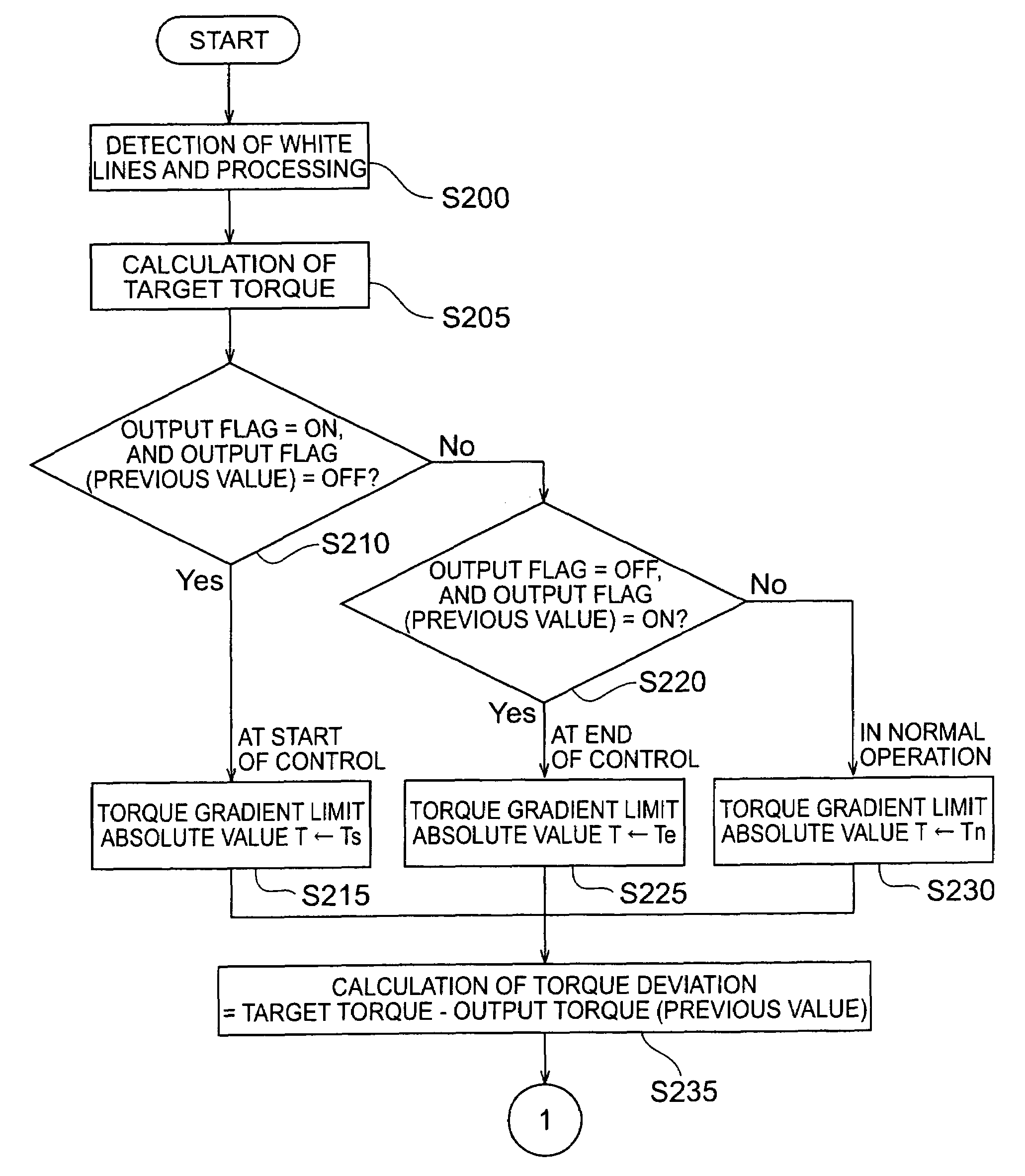
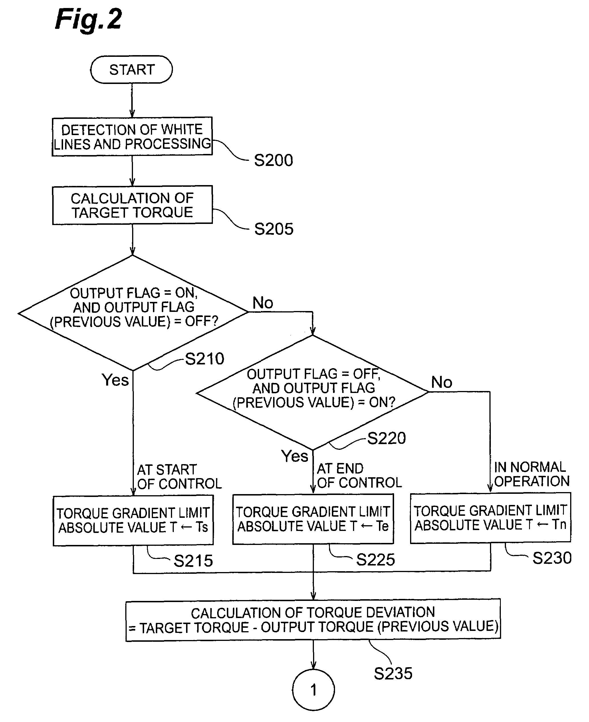
A driving support system according to the present invention is provided with an actuator for steering steered wheels of a vehicle and is used for supporting driving of the vehicle by making use of steering by means of the actuator. The driving support system has an image taking device for taking a forward image ahead the vehicle, a determiner for determining a controlled variable of the actuator on the basis of the forward image acquired by the image taking device, a limiter for limiting the controlled variable when a time change of the controlled variable of the actuator determined by the determiner is off a predetermined range, and a controller for controlling the actuator. The limiter sets a limit value for limiting the time change of the controlled variable of the actuator so that the limit value at a start (or at an end) of the driving support control is different from the limit value in continuation of the driving support control. In this configuration, the limit value to prevent a driver from sensing discomfort is set at the start (or at the end) of the driving support control, while the limit value suitable for the driving support control is set during continuous execution of the driving support control. This permits the system to achieve suppression of the discomfort at the start (or at the end) of the support control and improvement in performance of the support control in continuation of the control together.

Description

BACKGROUND OF THE INVENTION[0001]1. Field of the Invention[0002]The present invention relates to a driving support system and method with an actuator for steering steered wheels of a vehicle, which supports driving of the vehicle by means of the actuator.[0003]2. Related Background of the Invention[0004]There are known driving support systems (methods) arranged to take a forward image ahead a vehicle with a camera or the like, to detect a driving route of the vehicle on the basis of the taken image or video, and to support driving so as to prevent the vehicle from departing from the driving route, and they started to be mounted on commercially available cars. Such driving support systems are called lane keep (assist) systems or the like, and include those for simply drawing driver's attention in the event of a departure from the driving route, and those for actuating an actuator to steer the steered wheels in the event of a departure from the driving route (or assist steering), and ...

Claims


Application Information

Patent Timeline
Patent Type & Authority Patents(United States)
IPC IPC(8): A01B69/00B60R21/00B62D1/28B62D5/04B62D6/00B62D15/02B62D101/00B62D113/00B62D137/00H04N7/18
CPCB62D1/28B62D15/025B62D15/029
Inventor IWAZAKI, KATSUHIKOKAWAKAMI, SEIJINIWA, SATORUKATAOKA, HIROAKIRATTAPON, CHUMSAMUTR
Owner TOYOTA JIDOSHA KK
Learn More