
Conveyor system and method

a conveyor system and conveyor technology, applied in the field of conveyor systems, can solve the problems of requiring considerable labor and time to set up and install, and requiring considerable time to install, so as to facilitate the transportation and sorting of objects, reduce the set up and installation time, and be easy to be assembled and disassembled from one.

Active Publication Date: 2008-06-17
HYTROL CONVEYOR
View PDF9 Cites 9 Cited by
  • Summary
  • Abstract
  • Description
  • Claims
  • Application Information

AI Technical Summary

Benefits of technology

"The present invention provides a conveyor system for transporting and sorting objects that is easy to assemble and maintain. The system includes a plurality of lanes that are operable to convey and sort objects, as well as logic circuitry and distribution devices that are in communication with each other and with peripheral devices like sensors, solenoids, and motors. The system also includes troughs that secure the cables and protect them from damage. The conveyor system has the advantage of providing automated controls for various applications with a real-time response. Overall, the conveyor system simplifies the installation process, reduces the likelihood of damage to the cables, and provides a convenient technique to route cables between the logic circuitry and distribution devices."

Problems solved by technology

Hard wiring the conveyor systems requires considerable labor and time to set up and assemble, as a licensed electrician is needed to ensure that the hard wiring is set up correctly.
Furthermore, hard wiring the conveyor systems requires individually running the wires through conduit between logic circuitry and each of the peripheral devices, which also requires considerable time to install.
As such, these peripheral devices are typically more expensive than peripheral devices that do not need to provide identification information.
For instance, a conveyor system that sorts objects typically makes real-time decisions, such as diversion decisions, which would generally be more difficult to achieve with a networked sorter where each of the sensors would have to be scanned to first identify the sensor and determine the location of the sensor that sent an input signal necessitating the diversion decision.
In addition, there remains a need for a conveyor system that is cost effective and uncomplicated to assemble and disassemble.

Method used


Image

  • Conveyor system and method
  • Conveyor system and method
  • Conveyor system and method

Examples


Embodiment Construction

[0036]The present invention now will be described more fully hereinafter with reference to the accompanying drawings, in which some, but not all embodiments of the invention are shown. Indeed, this invention may be embodied in many different forms and should not be construed as limited to the embodiments set forth herein; rather, these embodiments are provided so that this disclosure will satisfy applicable legal requirements. Like numbers refer to like elements throughout.

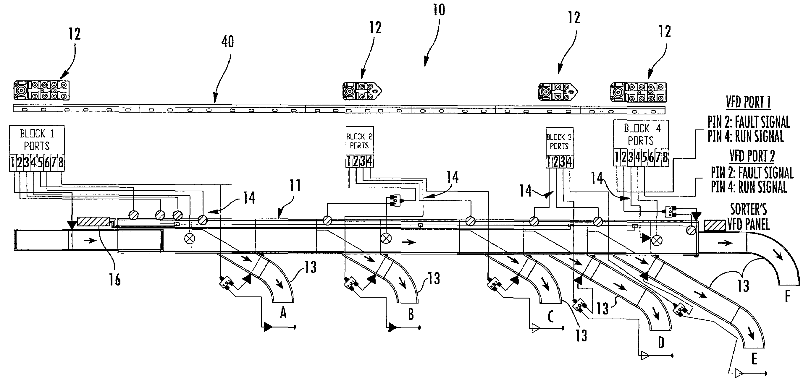
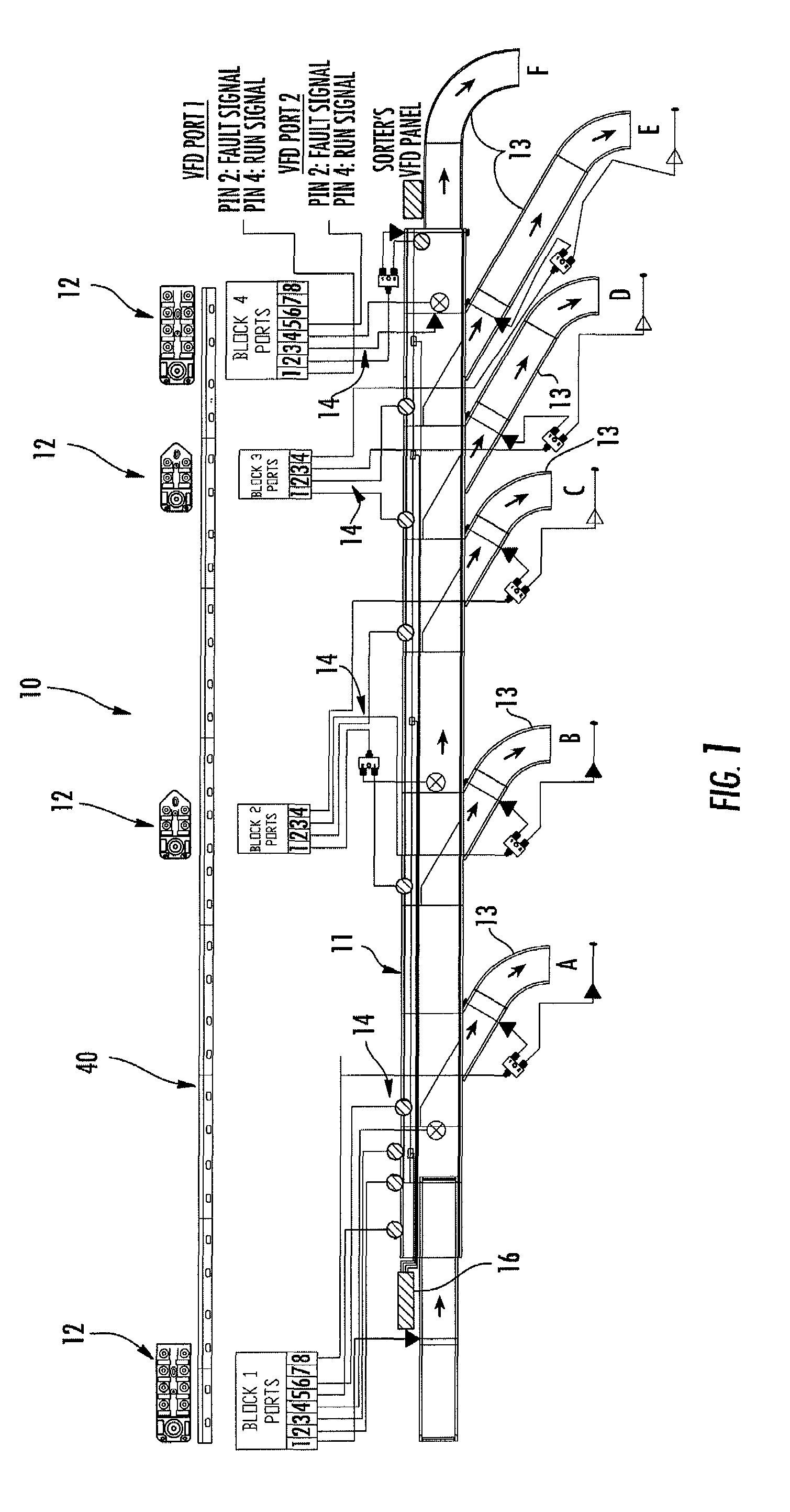
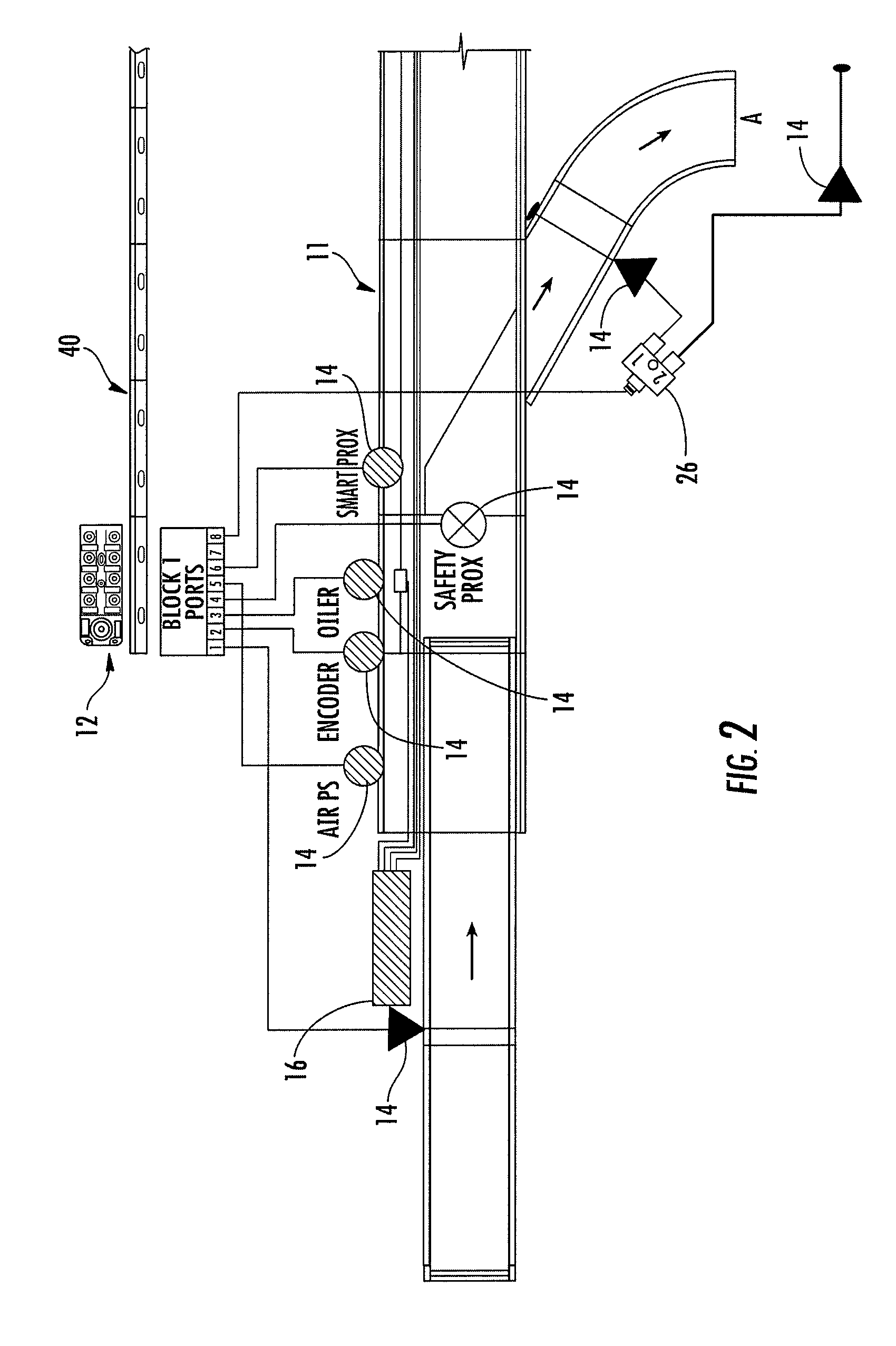
[0037]Referring to the figures, and in particular FIG. 1, there is shown a conveyor system 10. The conveyor system 10 includes main line 11 and a plurality of lanes connected in series to sort a variety of objects. In particular, the embodiment shown in FIG. 1 includes five lanes (identified by the letters A, B, C, D, and E) in addition to a discharge lane (identified by the letter F). The conveyor system 10 also includes a plurality of distribution devices 12 for receiving and distributing at least power and / or c...


PUM


Abstract

A conveyor system for sorting objects is provided. The conveyor system includes a plurality of lanes arranged in series with one another, wherein each of the lanes is operable to convey and sort a plurality of objects therealong. The conveyor system also includes at least one peripheral device associated with at least one of the lanes that is operable to facilitate the conveying and sorting of the objects. The system also includes logic circuitry in communication with the at least one peripheral device, as well as at least one distribution device in communication with the logic circuitry and the at least one peripheral device. Each distribution device includes a plurality of ports for receiving respective cables therein, and at least one cable couples the logic circuitry and the distribution device and at least one cable couples each peripheral device and the distribution device, wherein each of the cables are coupled without hard wiring.

Description

CROSS-REFERENCE TO RELATED APPLICATIONS[0001]The present application claims priority from U.S. Provisional Application No. 60 / 749,391 entitled “Conveyor System and Method,” filed Dec. 12, 2005, the contents of which is incorporated in its entirety herein by reference.BACKGROUND OF THE INVENTION[0002]1. Field of the Invention[0003]The present invention is directed to conveyor systems, and more particularly, to a system for sorting objects.[0004]2. Description of Related Art[0005]Conveyor systems are used to transport goods, packages, cartons and other objects in all types of environments and experience heavy use in the manufacturing and shipping industries. Complex conveyor systems typically require several conveyor lines and lanes that cooperate with one another to transport or sort objects, as well as various peripheral devices that are associated with each conveyor lane (e.g., sensors, solenoids, motors, etc.). As such, systems for networking and distributing the input / output (“I / ...

Claims


Application Information

Patent Timeline
Patent Type & Authority Patents(United States)
IPC IPC(8): B65G47/10
CPCG05B19/41845G05B2219/31009G05B2219/45047G05B2219/45054Y02P90/02
Inventor BONHAM, BOYCEPOTTER, RICHARDROGERS, WENDELLPALMER, CHUCK
Owner HYTROL CONVEYOR
Learn More