
Apparatus and method for providing a shielding means for an X-ray detection system

a technology of x-ray detection and apparatus, applied in material analysis using wave/particle radiation, nuclear engineering, instruments, etc., can solve the problems of light objects falling or even stopping on the conveyor bel

Inactive Publication Date: 2008-06-10
MORPHO DETECTION INC
View PDF15 Cites 16 Cited by
  • Summary
  • Abstract
  • Description
  • Claims
  • Application Information

AI Technical Summary

Benefits of technology

"The patent describes an apparatus and method for providing an x-ray shield in a computed tomography system. The apparatus includes a structure with an input opening and an outlet opening for receiving a gantry and an x-ray source. The structure has an internal volume with an x-ray shielding material. The method involves using a plurality of tubs with a peripheral wall and bottom that cover the input and outlet openings. The tubs also have an indicator for detection. The system can prevent the x-ray source from generating an x-ray beam unless the indicator is generated. The technical effect is to provide better protection against x-rays in a computed tomography system."

Problems solved by technology

However, these curtains may obstruct the flow of baggage on the conveyor as they may cause lighter objects (e.g., smaller bags, purses, carry on luggage, etc.) to tumble or even stop on the conveyor.

Method used


Image

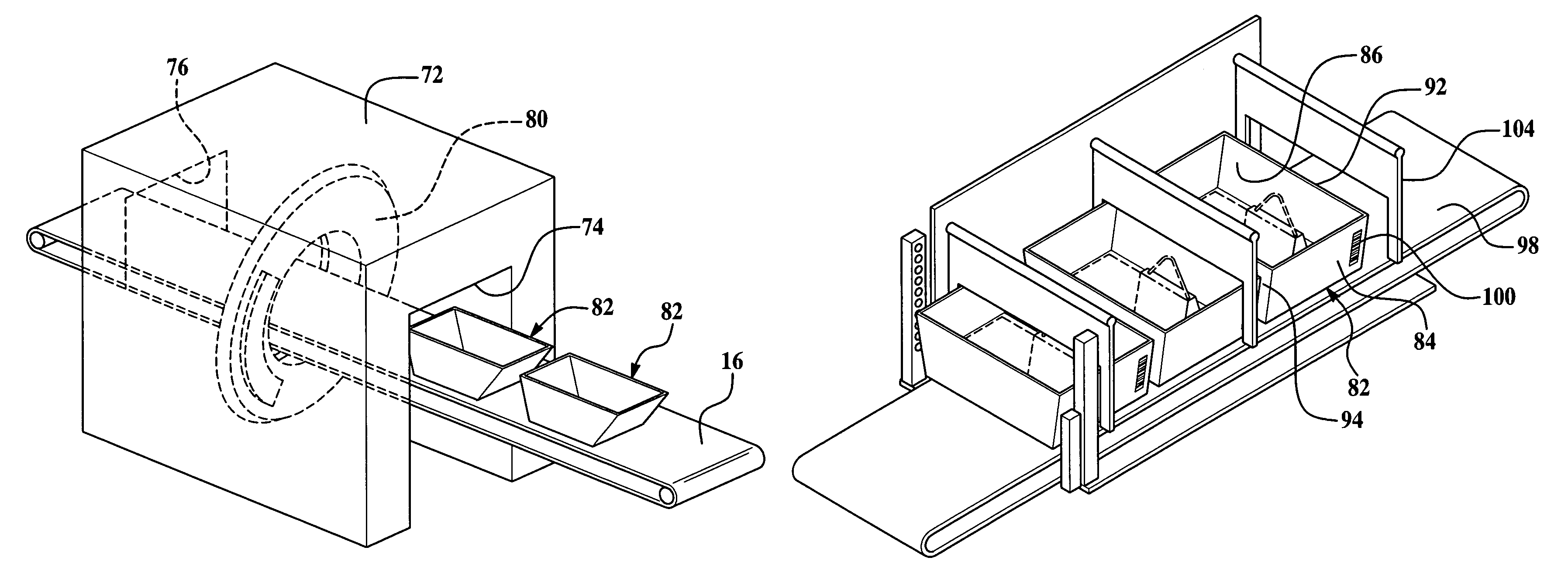
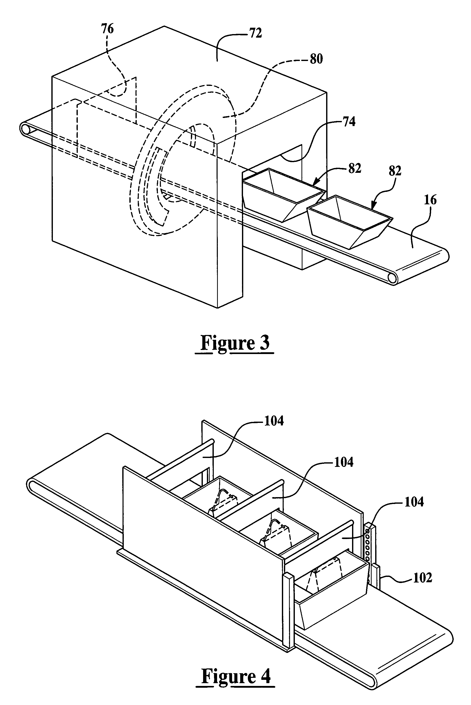
  • Apparatus and method for providing a shielding means for an X-ray detection system
  • Apparatus and method for providing a shielding means for an X-ray detection system
  • Apparatus and method for providing a shielding means for an X-ray detection system

Examples


Embodiment Construction

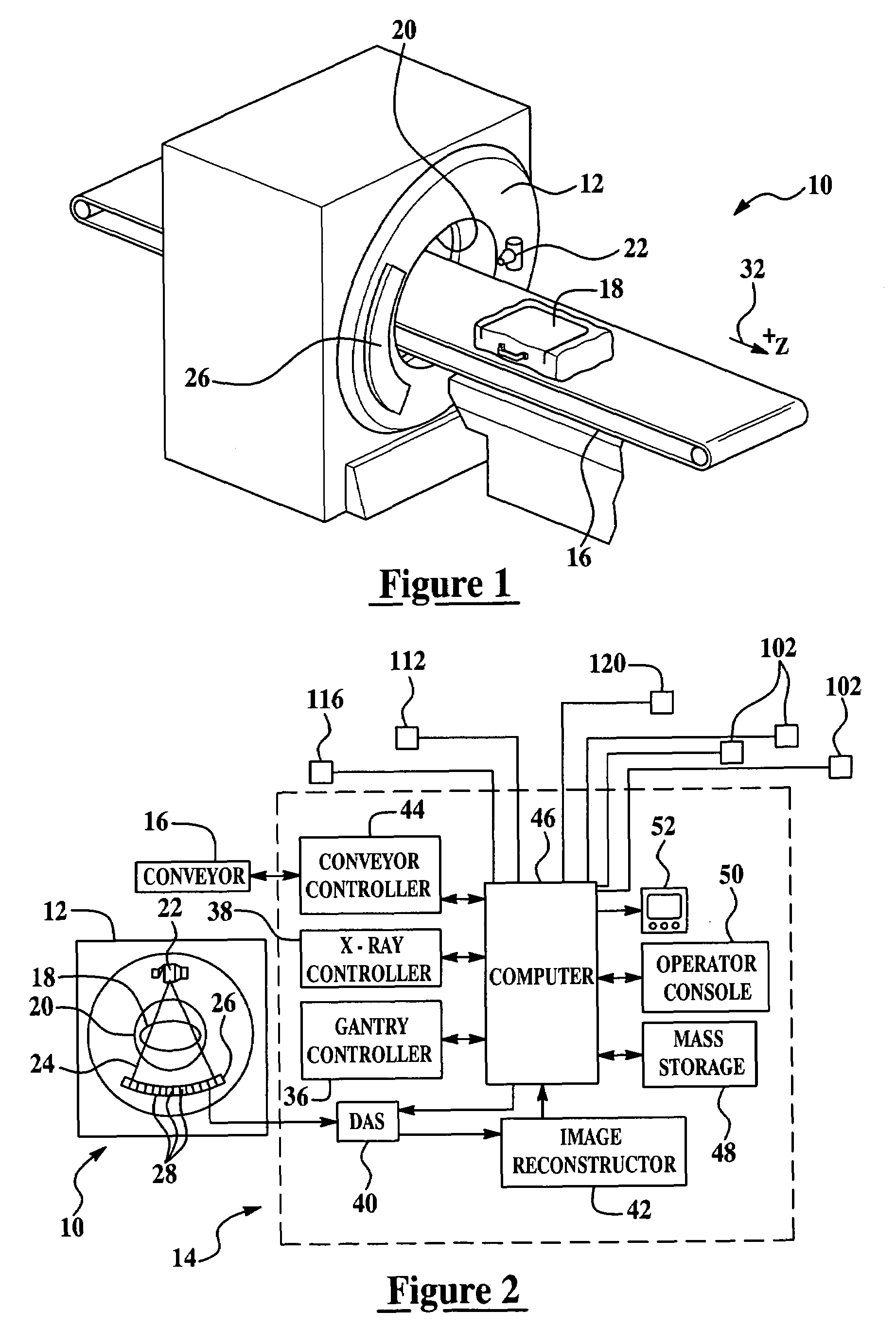
[0021]The disclosure of the present invention relates to an apparatus and method for providing a shielding means for use with x-ray detection systems. In particular, the shielding means is contemplated for use with security checkpoint systems configured to scan luggage, carry on luggage and other items being loaded onto an airplane.

[0022]Accordingly, exemplary embodiments of the present invention are directed to bins or tubs configured to hold the items being scanned while the bin or tub comprises a portion of the x-ray shielding of the scanning device. In addition, exemplary embodiments of the present invention are also contemplated to provide a method for determining when an object or tub is in the proper location for scanning and the appropriate shielding is in place. Moreover, additional exemplary embodiments provide methods for increasing the throughput of the scanning device.

[0023]Referring now to FIGS. 1 and 2, a computed tomography (CT) imaging system 10 is shown. FIGS. 1 an...


PUM

PropertyMeasurementUnit
computed tomographyaaaaaaaaaa
distanceaaaaaaaaaa
computed tomography scanneraaaaaaaaaa

Abstract

An apparatus and method for providing an x-ray shield means in an x-ray detection system. An x-ray inhibiting container for use in a computed tomography system is provided, the container comprising: a peripheral wall; and a bottom, wherein the peripheral wall and bottom define a receiving area, and a forward portion and a rearward portion of the peripheral wall comprise an x-ray inhibiting material. The system comprising: a computed tomography scanner, configured to produce x-ray projection data as an object is passed through the computed tomography scanner, the computed tomography scanner comprising: a gantry having an opening; and an x-ray source configured to project a fan beam of x-rays towards a detector array disposed on an opposite side of the gantry opening, the x-ray source and detector array being mounted to the gantry about the opening; a structure defining an internal volume being configured to receive at least the gantry of the computed tomography scanner therein, the structure having an input opening and an outlet opening, the structure comprising an x-ray shielding material; and a motorized conveyor for passing a plurality of tubs through the input opening to the outlet opening, wherein each of the tubs comprises a peripheral wall and a bottom to define a tub volume and a forward portion and a rearward portion of the peripheral wall is configured to substantially cover the input opening or the outlet opening as the plurality of tubs are passed through the structure, wherein the forward portion and the rearward portion each comprise an x-ray shielding material.

Description

BACKGROUND[0001]This present invention relates generally to an apparatus and method for scanning and inspecting baggage. More particularly, the present invention relates to security screening systems for use at airports.[0002]Carry-on baggage inspection systems generally utilize a scan projection (SP) image for presentation to the operator. In most baggage inspection systems, scan projection images are created by moving an object under a fan beam of x-rays from a stationary x-ray source.[0003]In some computed tomography (CT) imaging system configurations, an x-ray source projects a fan-shaped beam which is collimated to lie within an X-Y plane of a Cartesian coordinate system and generally referred to as an “imaging plane”. The x-ray beam passes through an object being imaged. The beam, after being attenuated by the object, impinges upon an array of radiation detectors. The intensity of the attenuated radiation beam received at the detector array is dependent upon the attenuation of...

Claims


Application Information

Patent Timeline
Patent Type & Authority Patents(United States)
IPC IPC(8): H05G1/00G01N23/083
CPCG01N23/046G01V5/0008G01N2223/419G01V5/20
Inventor GATTEN, RONALD A.
Owner MORPHO DETECTION INC
Learn More