
Combustion chamber control for combustion-powered fastener-driving tool

a technology of combustion chamber and combustion-powered fastener, which is applied in the direction of manufacturing tools, stapling tools, nailing tools, etc., can solve the problems of piston travel stopping, vacuum loss, and prolonging the service life of the chamber

Active Publication Date: 2008-06-10
ILLINOIS TOOL WORKS INC
View PDF7 Cites 43 Cited by
  • Summary
  • Abstract
  • Description
  • Claims
  • Application Information

AI Technical Summary

Benefits of technology

[0014]The above-listed needs are met or exceeded by the present combustion-powered fastener-driving tool which overcomes the limitations of the current technology. Among other things, the present tool incorporates an electromechanical, or alternately, a purely mechanical mechanism configured for managing the chamber lockout that controls the length of time needed for vacuum piston return.

Problems solved by technology

This causes the vacuum to be lost and piston travel will stop before reaching the top of the cylinder.
It is disadvantageous to maintain the chamber closed longer than the minimum time to return the piston, as cooling and purging of the tool is prevented.
The main deficiency of this approach is that the piston requires the use of a manual reset rod to return the piston to pre-firing if the piston does not fully return due to a nail jam or perhaps a dirty / gummy cylinder wall.
A piston that does not return will cause the chamber to remain closed; therefore the tool cannot be fired again.

Method used


Image

  • Combustion chamber control for combustion-powered fastener-driving tool
  • Combustion chamber control for combustion-powered fastener-driving tool
  • Combustion chamber control for combustion-powered fastener-driving tool

Examples


Embodiment Construction

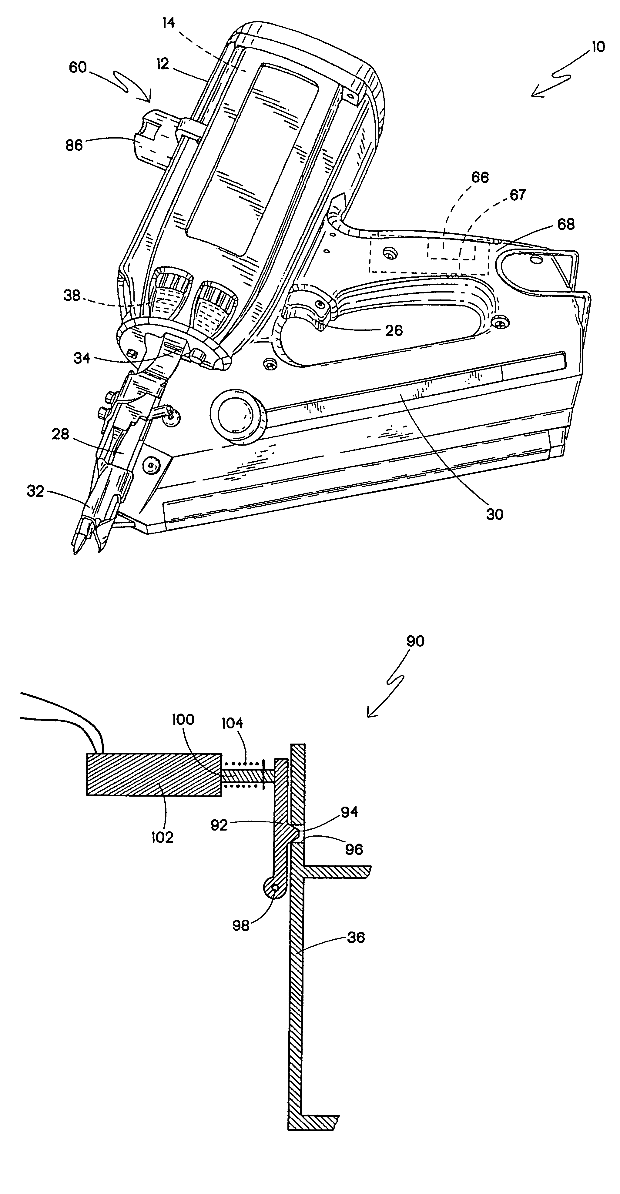
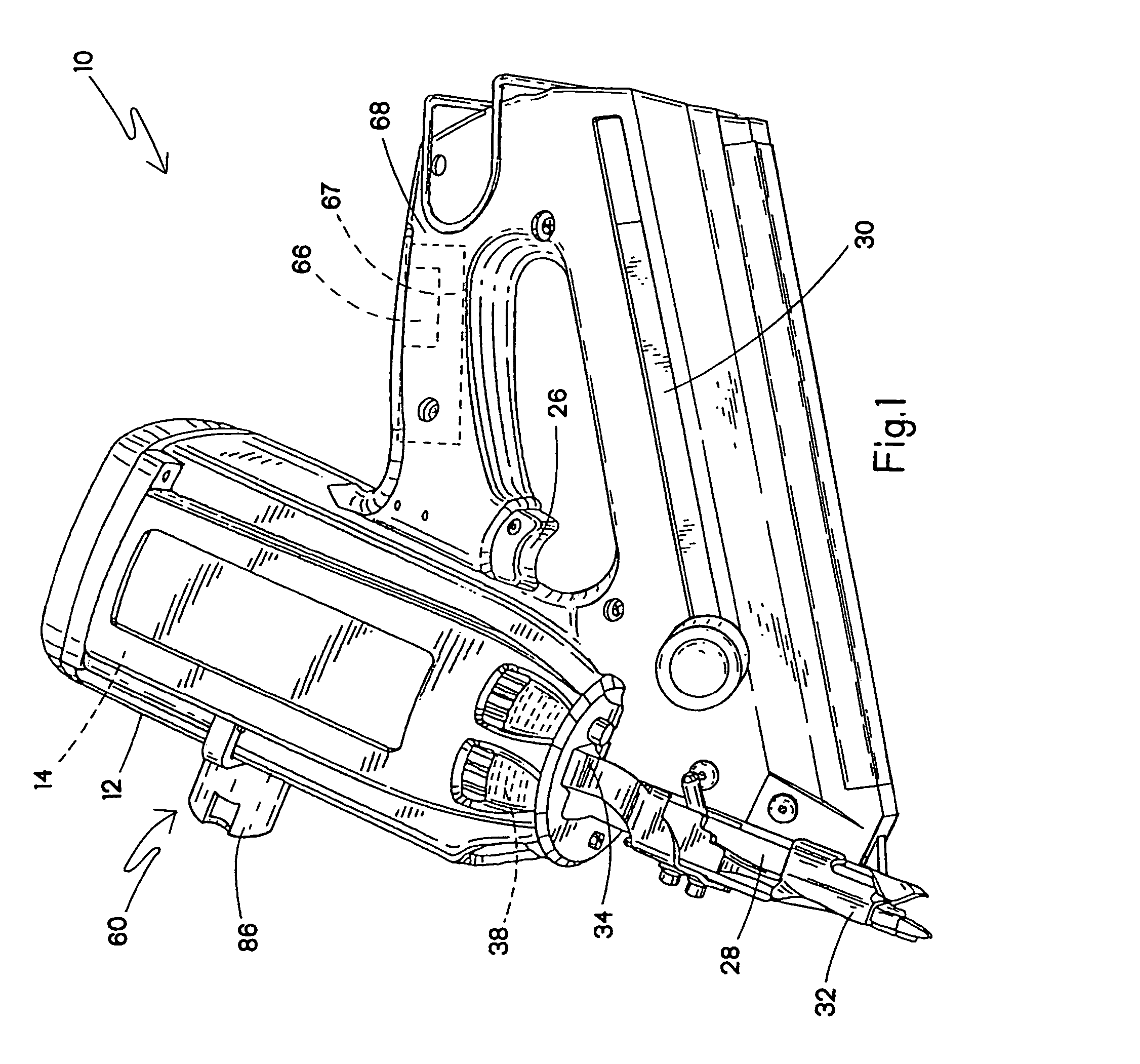
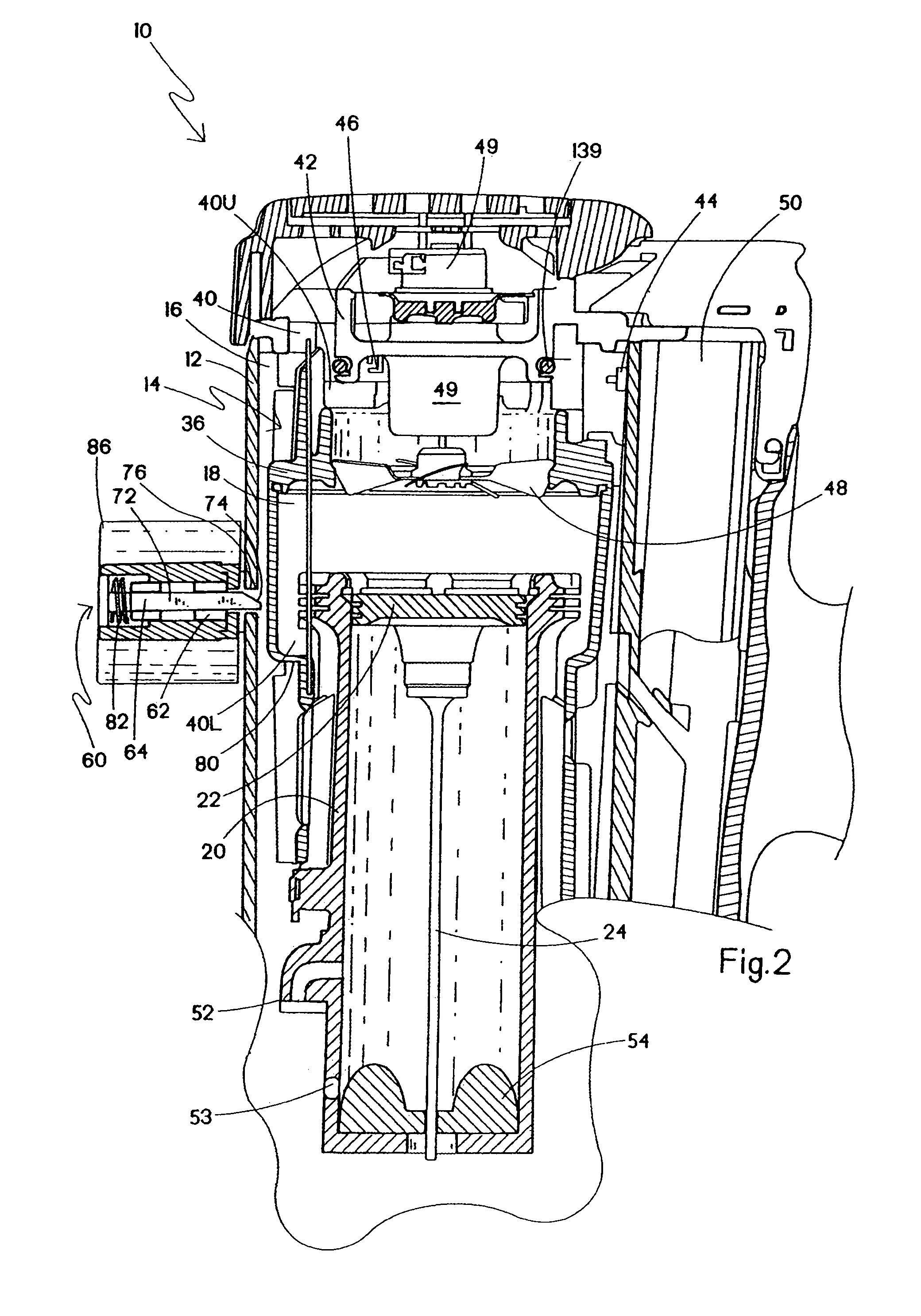
[0030]Referring now to FIGS. 1-3, a combustion-powered fastener-driving tool incorporating the present invention is generally designated 10 and preferably is of the general type described in detail in the patents listed above and incorporated by reference in the present application. A housing 12 of the tool 10 encloses a self-contained internal power source 14 (FIG. 2) within a housing main chamber 16. As in conventional combustion tools, the power source 14 is powered by internal combustion and includes a combustion chamber 18 that communicates with a cylinder 20. A piston 22 reciprocally disposed within the cylinder 20 is connected to the upper end of a driver blade 24. As shown in FIG. 2, an upper limit of the reciprocal travel of the piston 22 is referred to as a pre-firing position, which occurs just prior to firing, or the ignition of the combustion gases which initiates the downward driving of the driver blade 24 to impact a fastener (not shown) to drive it into a workpiece.

[...


PUM

PropertyMeasurementUnit
volumeaaaaaaaaaa
pressuresaaaaaaaaaa
accelerationaaaaaaaaaa

Abstract

A combustion-powered fastener-driving tool includes a combustion-powered power source, a valve sleeve reciprocable relative to the power source between a rest position and a firing position, and a lockout device in operational proximity to the valve sleeve and configured for automatically preventing the reciprocation of the valve sleeve from the firing position until a piston in the power source returns to a pre-firing position.

Description

RELATED APPLICATION[0001]This application claims priority under 35 USC §120 from U.S. Ser. No. 60 / 543,053, filed Feb. 9, 2004 and also from U.S. Ser. No. 11 / 028,432, filed Jan. 3, 2005.BACKGROUND[0002]The present invention relates generally to fastener-driving tools used to drive fasteners into workpieces, and specifically to combustion-powered fastener-driving tools, also referred to as combustion tools.[0003]Combustion-powered tools are known in the art. Exemplary tools are manufactured by Illinois Tool Works, Inc. of Glenview, Ill. for use in driving fasteners into workpieces, and are described in commonly assigned patents to Nikolich U.S. Pat. Re. No. 32,452, and U.S. Pat. Nos. 4,522,162; 4,483,473; 4,483,474; 4,403,722; 5,133,329; 5,197,646; 5,263,439 and 6,145,724 all of which are incorporated by reference herein.[0004]Such tools incorporate a generally pistol-shaped tool housing enclosing a small internal combustion engine. The engine is powered by a canister of pressurized f...

Claims


Application Information

Patent Timeline
Patent Type & Authority Patents(United States)
IPC IPC(8): B21J15/28B25C1/04
CPCB25C1/08
Inventor MOELLER, LARRY M.DOHERTY, JAMES E.FABIN, JOSEPH E.
Owner ILLINOIS TOOL WORKS INC
Learn More