
Technique for detecting corruption associated with a stack in a storage device

Inactive Publication Date: 2008-05-27
SAMSUNG ELECTRONICS CO LTD
View PDF16 Cites 50 Cited by
  • Summary
  • Abstract
  • Description
  • Claims
  • Application Information

AI Technical Summary

Benefits of technology

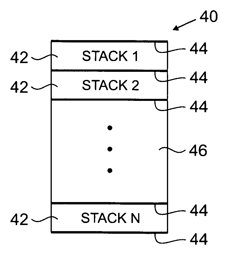
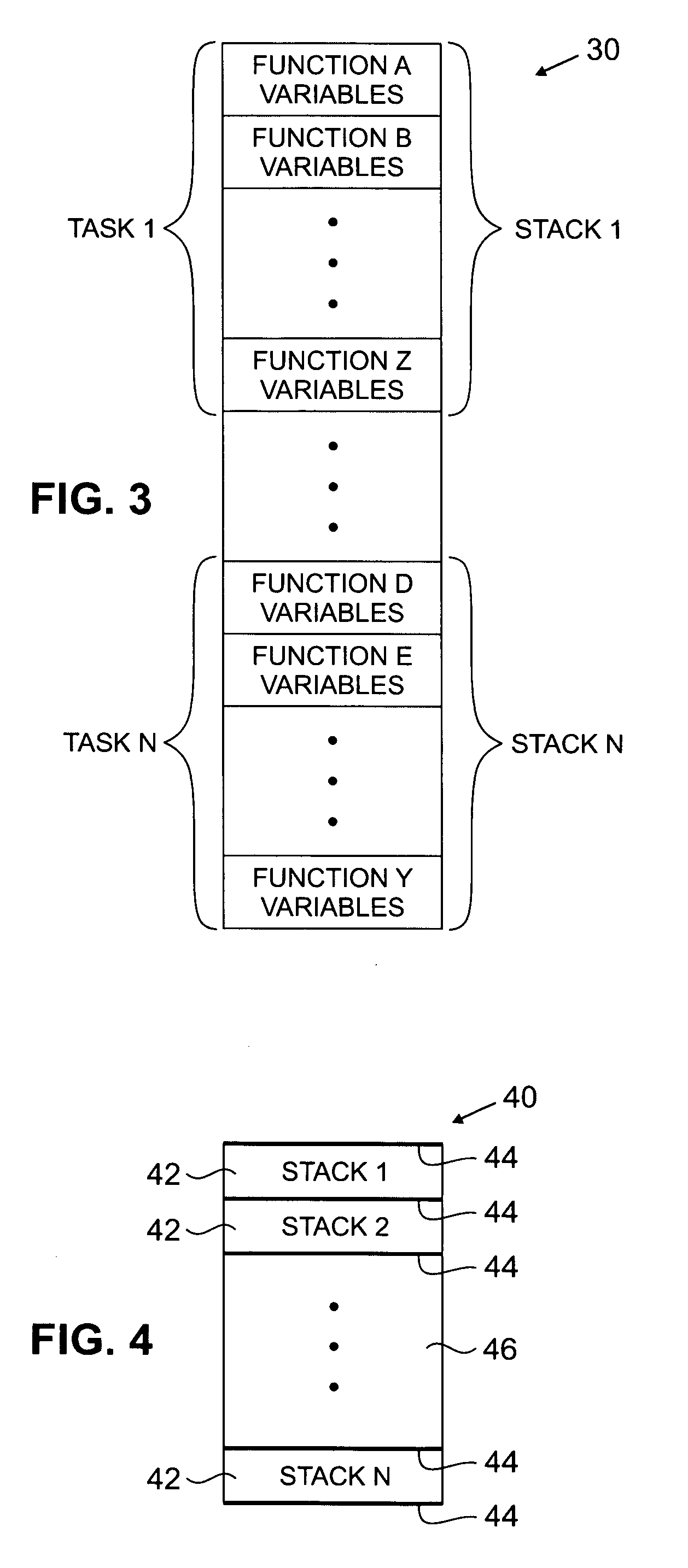
[0016]In one aspect of the present invention, the processing device inserts a first quantity of information adjacent to a top of the stack in the storage device, and inserts a second quantity of information adjacent to the bottom of the stack in the storage device. This aspect of the present invention allows both stack overflow and stack underflow conditions to be detected.

Problems solved by technology

The corruption associated with the stack can arise as a result of a faulty task, function, or the stack itself.

Method used


Image

  • Technique for detecting corruption associated with a stack in a storage device
  • Technique for detecting corruption associated with a stack in a storage device
  • Technique for detecting corruption associated with a stack in a storage device

Examples


Embodiment Construction

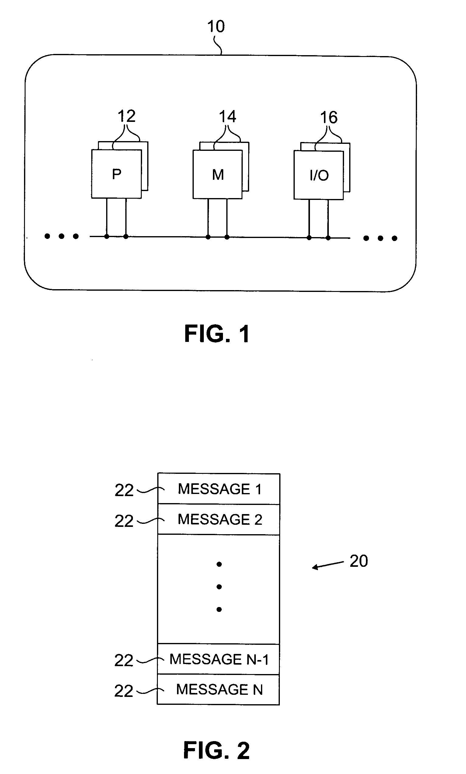
[0022]Referring to FIG. 1, there is shown a processing system 10 including at least one processor (P) 12, memory (M) 14, and input / output (I / O) interface 16, connected to each other by a bus 18, for facilitating the implementation of a multi-tasking environment in accordance with the present invention. In such a multi-tasking environment, the processor 12 typically performs a task by retrieving a message from a message queue and processing the message by calling, or invoking, one or more specific functions which are required to perform the task based upon information contained in a message. A message typically identifies an event which is received by the processing system 10 through the input / output interface 16. Alternatively, a message can identify an event which occurs within the processing system 10. In any case, each message is typically stored in the message queue in the order it is received or in the order of occurrence of the corresponding event, which are often one in the s...


PUM


Abstract

A technique for detecting corruption associated with a stack in a storage device is disclosed. In one embodiment, the technique is realized by having a processing device insert a quantity of information adjacent to the stack in the storage device, wherein the quantity of information has an initial state. The processing device then inspects the quantity of information so as to identify any deviation from the initial state and thereby detect corruption associated with the stack in the storage device.

Description

BACKGROUND OF THE INVENTION[0001]1. Field of the Invention[0002]The present invention relates generally to multi-tasking systems and, more particularly, to a technique for detecting corruption associated with a stack in a storage device.[0003]2. Background of the Present Invention[0004]A real time embedded system often provides a multi-tasking environment in order to meet diverse application requirements. In a multi-tasking environment, an individual stack (i.e., an individual work space) is typically required for each task. Each stack provides a location, or a group of locations, where dynamic function variables may be stored as needed for a corresponding task. Typically, each stack is allocated a dedicated range of sequential memory, although a stack can also be allocated a dedicated space of non-sequential memory. Regardless, stacks have always had problems in the areas of overflow and underflow.[0005]Stack overflow occurs when the stack memory is insufficient to meet workload de...

Claims


Application Information

Patent Timeline
IPC IPC(8): G06F9/46G06F5/06
CPCG06F11/073G06F11/0763G06F21/52G06F5/06
Inventor LOVETTE, STEVEN EUGENE
Owner SAMSUNG ELECTRONICS CO LTD
Learn More