
Polarization diversity detection without a polarizing beam splitter

a polarization beam and beam splitter technology, applied in the field of optical measurements, can solve the problems of stray reflections, inability to easily and inexpensively alter to operate at a non-standard wavelength, and high cost, and achieve the effects of low loss, significant cost reduction, and clean time domain measurements

Inactive Publication Date: 2008-05-27
INTUITIVE SURGICAL OPERATIONS INC
View PDF8 Cites 16 Cited by
  • Summary
  • Abstract
  • Description
  • Claims
  • Application Information

AI Technical Summary

Problems solved by technology

But there are drawbacks with using polarizing beam splitters.
First, they are bulky and expensive.
Second, polarizing beam splitters add stray reflections to the detected signals.
Third, if the polarizing beam splitter is designed to operate in a particular wavelength, e.g., 1500 nm, it cannot be easily and inexpensively altered to operate at a non-standard wavelength, such as 800 nm, at least as compared to a standard optical coupler.

Method used


Image

  • Polarization diversity detection without a polarizing beam splitter
  • Polarization diversity detection without a polarizing beam splitter
  • Polarization diversity detection without a polarizing beam splitter

Examples


Embodiment Construction

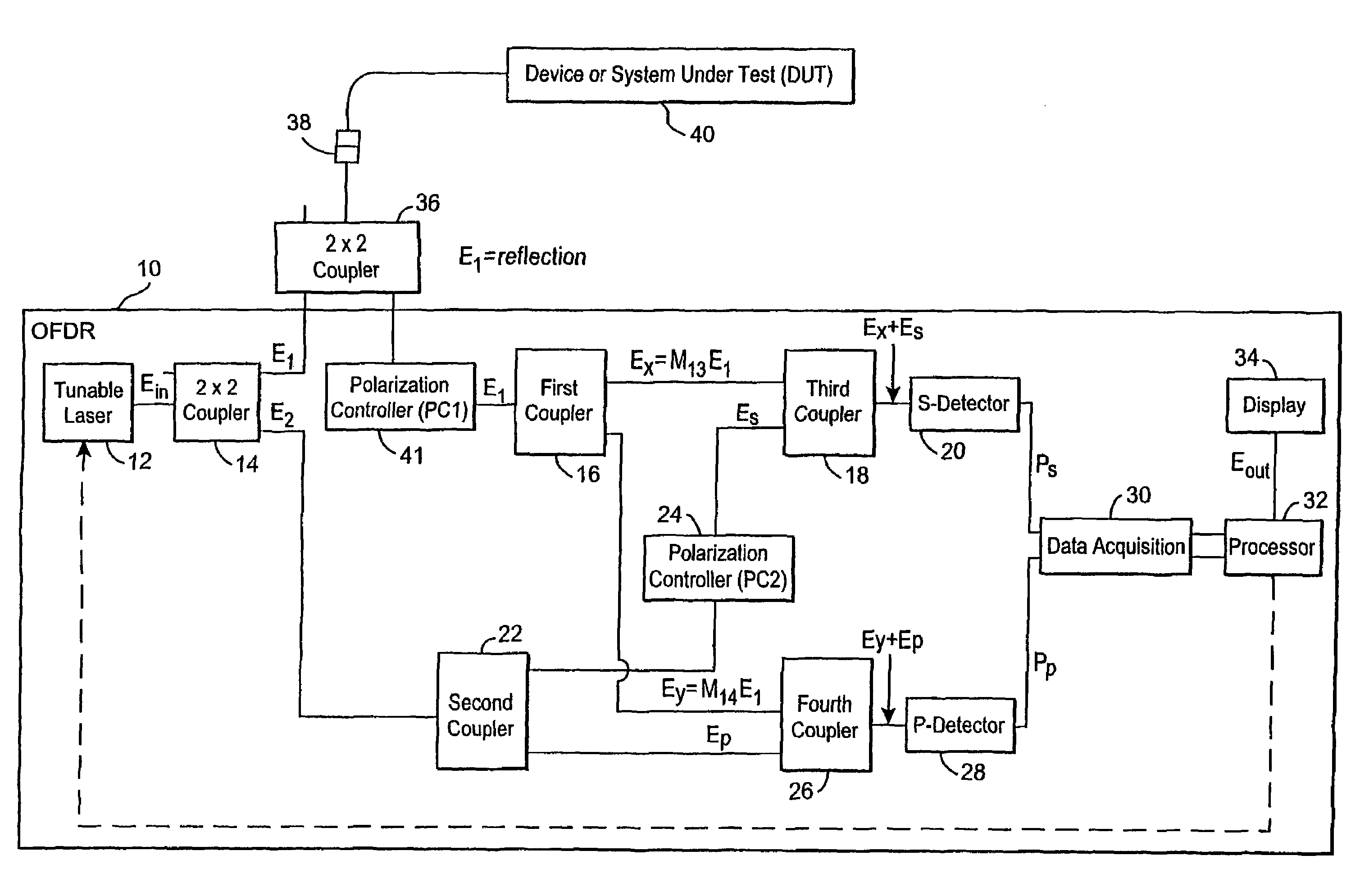
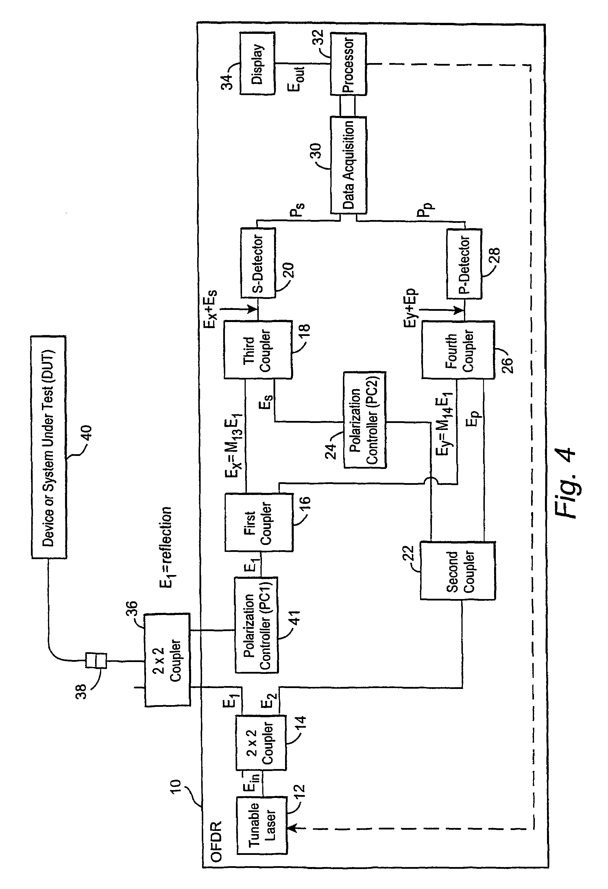
[0030]The following description, for purposes of explanation not limitation, sets forth specific details, such as particular components, electronic circuitry, techniques, etc. But it will be apparent to one skilled in the art that the present technology may be practiced in other embodiments that depart from these specific details. In other instances, detailed descriptions of well-known methods, devices, and techniques, etc. are omitted so as not to obscure the description with unnecessary detail. Individual function blocks are shown in the figures. Those skilled in the art will appreciate that functions may be implemented using discrete components or multi-function hardware. Processing functions may be implemented using a programmed microprocessor or general-purpose computer, using an application specific integrated circuit (ASIC), andlor using one or more digital signal processors (DSPs).

[0031]A first, non-limiting, example OFDR embodiment that does not employ a polarizing beam spl...


PUM

PropertyMeasurementUnit
propagation timeaaaaaaaaaa
longitudeaaaaaaaaaa
longitudeaaaaaaaaaa

Abstract

A fiber optic measurement device including an optical frequency domain reflectometer (OFDR) performs polarization diversity detection without using a polarizing beam splitter.

Description

CLAIM OF BENEFIT OF PROVISIONAL PATENT APPLICATION[0001]Priority is claimed from U.S. Provisional Patent Application No. 60 / 394,260, filed on Jul. 9, 2002. The contents of this provisional application are incorporated by reference.[0002]This application is the US national phase of international application PCT / US2003 / 021336 filed Jul. 8, 2003, the entire content of which is hereby incorporated by reference.RELATED APPLICATIONS[0003]This application is related to commonly-assigned U.S. application Ser. No. 10 / 520,818, entitled “Heterodyne Optical Spectrum Analyzer,” filed on Jul. 8, 2003, and to commonly-assigned, U.S. patent application Ser. No. 10 / 005,819, entitled “Apparatus and Method for the Complete Characterization of Optical Devices Including Loss, Birefringence, and Dispersion Effects,” filed on Dec. 14, 2001, now U.S. Pat. No. 6,856,400.FIELD OF THE INVENTION[0004]The present invention relates to optical measurements, and more particularly, to a device and method for perfor...

Claims


Application Information

Patent Timeline
Patent Type & Authority Patents(United States)
IPC IPC(8): G01N21/00G01M11/00
CPCG01M11/3172G01M11/3181G01M11/331G01M11/337
Inventor FROGGATT, MARK ESOLLER, BRIAN JWOLFE, MATTHEW S
Owner INTUITIVE SURGICAL OPERATIONS INC
Learn More