
Bat having a sleeve with holes

a bat and sleeve technology, applied in the field of baseball bats, can solve the problems of reducing affecting the performance of the target area, so as to achieve less stiffness and prevent rough surfaces

Active Publication Date: 2008-05-27
MIKEN SPORTS
View PDF54 Cites 11 Cited by
  • Summary
  • Abstract
  • Description
  • Claims
  • Application Information

AI Technical Summary

Benefits of technology

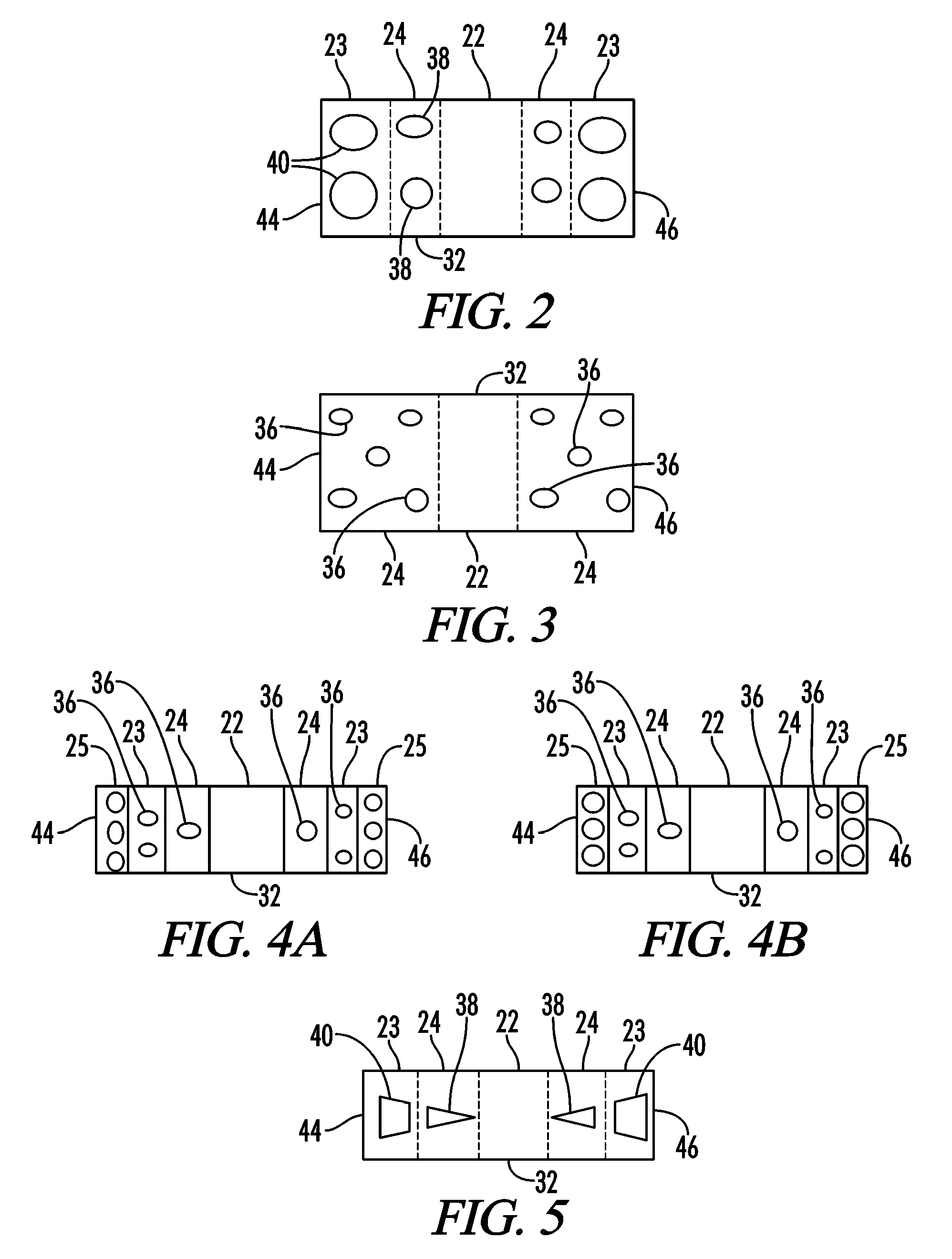
[0011]Disclosed herein is a bat comprising a handle portion, a transition portion attached to the handle portion, and a barrel portion attached to the transition portion. The barrel portion includes one or more first cross-sections having a first stiffness and a plurality of second cross-sections having a second stiffness. Each first cross-section is beside one second cross-section or between two of the second cross-sections and the first stiffness is greater than the second stiffness. The variance in stiffness between the first cross-sections and the second cross-sections is created by varying the amount of material in the cross-section or by, more accurately, removing material in the second cross sections to make the second cross-sections more flexible by creating holes. Likewise, a bat may be provided with third cross sections on the sides of the second cross-sections distal from the first cross-section whereby the third cross-sections are less stiff than the second cross-sections because more material is removed. Spacers may be added to holes to prevent rough surfaces and gaps.
[0012]It is therefore a general object of the present invention to provide a bat having variable wall stiffness.

Problems solved by technology

As the prior art bats have increased the performance in this area, many of the sports regulatory agencies have placed performance and / or configuration restrictions on the bats.
As such, the current maximum performance for the bat in its preferred hitting area is limited by these regulations.
However, it is also to be understood that the area to either side of the sweet spot on a prior art bat has a significant drop off in performance.
However, these attempts have drawback.
However, this patent application publication fails to reduce the thickness of any wall within the bat in order to increase performance of the bat.
As such, this patent application publication increases the weight of the bat in an attempt to increase the performance of the bat, which is counter productive.
This patent application publication also increases the cost of the bat by increasing the amount of material used.
Additionally, when there is a portion of a bat that has a change in diameter, that portion becomes a weakened spot.
Additionally, the differences in spacing between portions of the body and of the frame can create weaknesses.
Further, the differences in distance between the body and frame can cause manufacturing issues as to how to fill the variable distances and how to maintain the variable distances during construction of the bat.
Further, this published application discloses placing slots in one end of the bat to reduce the diameter of that end of the insert to more easily place an insert into a bat frame but fails to understand the benefits of placing the slots in both end of the sleeve as to increasing the flexibility of the bat hitting portion beyond the center of the barrel.
Further, the slots are not sufficient in length to increase the size of the sweet spot.

Method used


Image

  • Bat having a sleeve with holes
  • Bat having a sleeve with holes
  • Bat having a sleeve with holes

Examples


Embodiment Construction

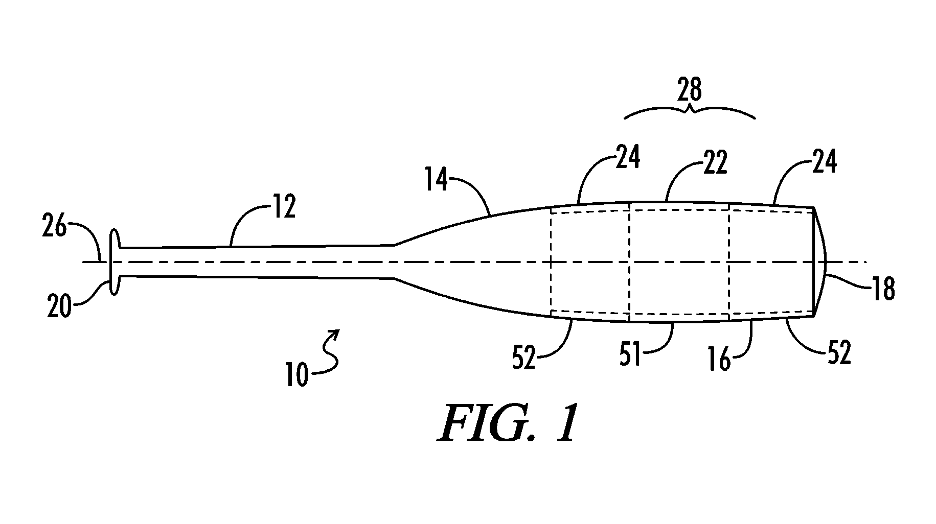
[0032]Referring generally now to FIGS. 1 and 3, there is shown generally at 10 one embodiment of the bat of the present invention. The bat 10 comprises a handle portion 12, a transition portion or taper portion 14, and a barrel portion 16. The transition portion 14 is preferably attached to the handle portion 12, while the barrel portion 16 is attached to the transition portion 14. An end cap 18 is traditionally placed on the end of the barrel portion 16 distal from the taper 14. A knob 20 is traditionally attached to the handle 12 on the end of the handle 12 distal from the barrel portion 16. Each bat has a preferred hitting section 28 that can also be called the sweet spot. In a traditional bat, the preferred hitting portion 28 lies in the middle portion of the barrel portion. For the purposes of this application, the area proximal the central part of the barrel portion 16 is the first cross-section 22. The area on either or both sides of the barrel portion will be called the seco...


PUM


Abstract

Disclosed herein is a bat comprising a handle portion, a transition portion attached to the handle portion, and a barrel portion attached to the transition portion. The barrel portion includes one or more first cross-sections having a first stiffness and a plurality of second cross-sections having a second stiffness. Each first cross-section is beside one second cross-section or between two of the second cross-sections and the first stiffness is greater than the second stiffness. The variance in stiffness between the first cross-sections and the second cross-sections is created by varying the amount of material in the cross-section or by, more accurately, removing material in the second cross sections to make the second cross-sections more flexible by creating holes.

Description

[0001]This is a continuation application claiming priority based upon co-pending U.S. patent application Ser. No. 11 / 243,120 filed Oct. 4, 2005 entitled “Bat Having A Sleeve With Holes”, which is a continuation-in-part application claiming priority based upon U.S. patent application Ser. No. 11 / 135,315 filed May 23, 2005 entitled “Bat with Enlarged Sweet Spot”, both of which are hereby incorporated by reference in their entireties.[0002]A portion of the disclosure of this patent document contains material that is subject to copyright protection. The copyright owner has no objection to the facsimile reproduction by anyone of the patent document or the patent disclosure, as it appears in the U.S. Patent and Trademark Office patent file or records, but otherwise reserves all copyright rights whatsoever.[0003]All patents and publications discussed herein are hereby incorporated by reference in their entirety.BACKGROUND OF THE INVENTION[0004]The present invention relates generally to bas...

Claims


Application Information

Patent Timeline
Patent Type & Authority Patents(United States)
IPC IPC(8): A63B59/06
CPCA63B59/06A63B59/0088A63B2209/02A63B2102/18A63B59/50A63B60/50A63B59/58
Inventor VACEK, MATTHEW V.MATHEW, BUJI
Owner MIKEN SPORTS
Learn More