
Electromagnetic contractor for controlling an electric starter

a technology of electric starter and contractor, which is applied in the direction of electromagnets, non-polarised relays, cores/yokes, etc., can solve the problems of insufficient mechanical rigidity, assembly assembly falling apart, and ovalization of the case, so as to increase the rigidity of the case 11 and support stability. , the effect of preventing any deformation

Active Publication Date: 2008-05-20
VALEO EQUIP ELECTRIC MOTEUR
View PDF5 Cites 11 Cited by
  • Summary
  • Abstract
  • Description
  • Claims
  • Application Information

AI Technical Summary

Benefits of technology

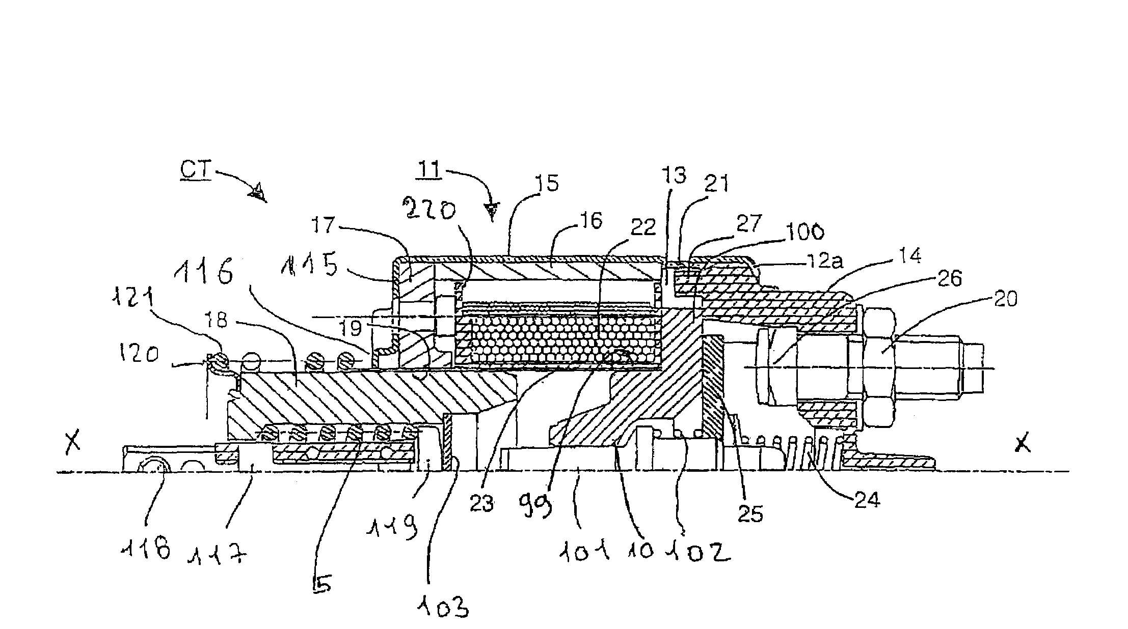
The invention is a starter contactor with reinforced mechanical strength, regardless of the tightening torque exerted on the connection terminals. The metal housing of the case has an annular rib that ensures the locking of the different parts of the case and increases the rigidity of the case, preventing any deformation due to the torque exerted on the cap when the connection terminals are tightened. The rib can serve as a centerer for the stationary core so that the quantity of material of the core can be reduced. The main stationary core is provided with radial cavities in which serrations of the housing are embedded during the crimping operation. The cap includes at least an axial stud intended to engage in a notch of the stationary core during assembly of the cap on the end of the housing. Other aspects and advantages of the invention will be apparent from the following description and the appended claims.

Problems solved by technology

When the case is produced by stacking several elements, careless handling of the case can result in a risk of the assembly coming apart.
This situation could occur in the event of insufficient mechanical rigidity of a case obtained by stamping a thin (0.5 to 1.5 mm) sheet of metal.
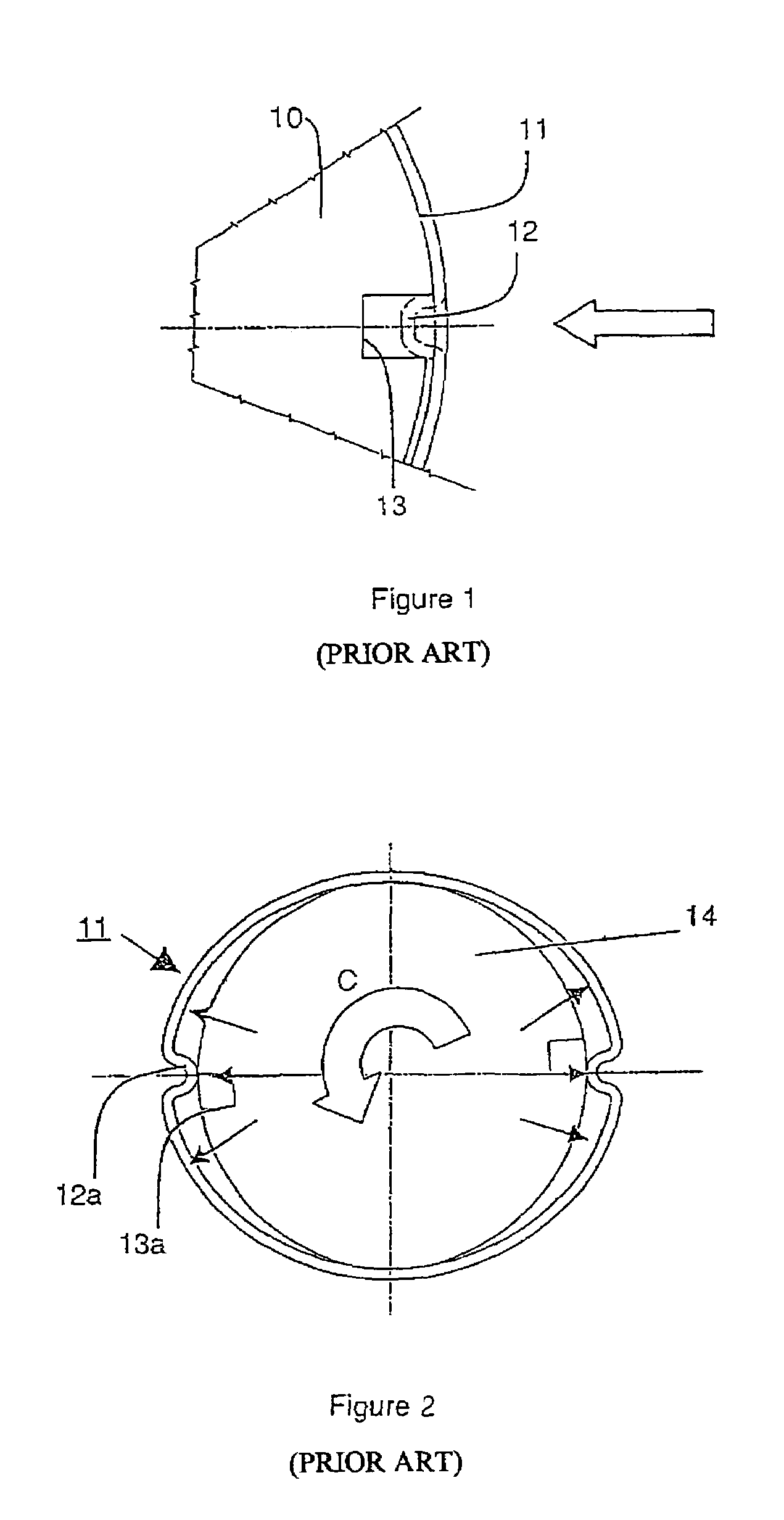
The risk of ovalization of the case due to the action of a heavy rotation torque is then possible, and the function of immobilizing the case from rotation is no longer ensured.

Method used


Image

  • Electromagnetic contractor for controlling an electric starter
  • Electromagnetic contractor for controlling an electric starter
  • Electromagnetic contractor for controlling an electric starter

Examples


Embodiment Construction

[0053]Exemplary embodiments of the invention will be described with reference to the accompanying figures. Like items in the figures are shown with the same reference numbers. In embodiments of the invention, numerous specific details are set forth in order to provide a more thorough understanding of the invention. However, it will be apparent to one of ordinary skill in the art that the invention may be practiced without these specific details. In other instances, well-known features have not been described in detail to avoid obscuring the invention.

[0054]Embodiments of the invention relate to an electromagnetic contactor for an electric starter motor.

[0055]In FIG. 3 the movable core 18 is in the rest position so that the axial air gap between the stationary core 10 and the movable core 18 is at a maximum.

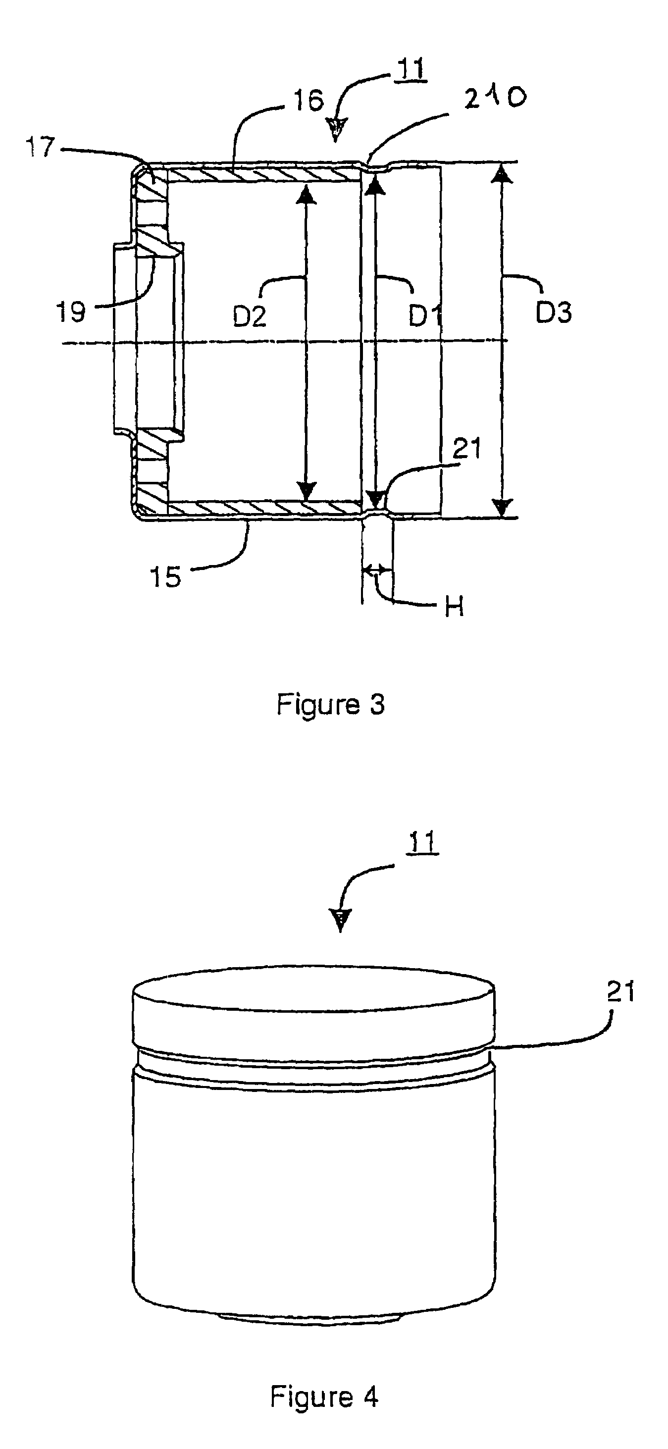
[0056]In FIGS. 3 to 5, the case 11 is formed from several elements, comprising a bell-shaped metal housing 15, an internal cylindrical ferrule 16 of mild steel, and a washer 17 of...


PUM


Abstract

The metal housing of the case of a contactor includes an annular rib extending continuously opposite the cylindrical periphery of the main stationary core, the rib having an internal diameter respectively greater than that of the ferrule and smaller than that of the housing, so as to ensure the locking of the different parts of the case and the crimping of the housing on the stationary magnet following local deformations exerted on the reduced diameter of the swaged part defining the rib.

Description

BACKGROUND OF THE INVENTION [0001]1. Field of the Invention[0002]The invention relates to an electromagnetic contactor for an electric starter motor, said contactor comprising:[0003]connection terminals intended for connection to the battery and to the electric motor,[0004]a movable core,[0005]a main stationary core,[0006]an axial air gap provided between the movable core and the main stationary core,[0007]a tubular coil to produce a magnetic current in the air gap provided between the movable core and a main stationary core during excitation,[0008]a magnetic circuit provided with a case constructed with magnetic frame attached to the stationary core,[0009]an insulating cap enclosing the contacts of the electric power circuit and having connection terminals,[0010]said case being composed of a metal bell-shaped housing, an internal ferrule made of magnetic material surrounding the coil, and a washer acting as an additional stationary core through which the movable core passes, and ar...

Claims


Application Information

Patent Timeline
Patent Type & Authority Patents(United States)
IPC IPC(8): H01H67/02B62J99/00F02N15/06H01H50/36H01H51/06
CPCF02N15/067H01H51/065H01H50/36F02N15/06F02N11/00H01H51/06
Inventor TALON, FREDERICMAGNIER, PIERREGRUET, CHRISTOPHE
Owner VALEO EQUIP ELECTRIC MOTEUR
Learn More