
Inductively charged battery pack

a technology of inductive charging and battery pack, which is applied in the direction of liquid/fluent solid measurement, instruments, transportation and packaging, etc., can solve the problems of wasting space in cases, affecting the efficiency and limited time period, so as to maximize the flexibility, efficiency or safety of inductive charging solutions

Active Publication Date: 2008-05-20
MICROSOFT TECH LICENSING LLC
View PDF18 Cites 502 Cited by
  • Summary
  • Abstract
  • Description
  • Claims
  • Application Information

AI Technical Summary

Benefits of technology

The present invention provides an inductive charging arrangement that makes it convenient for users to charge their mobile electronic devices and communication devices wirelessly. The arrangement allows for flexible, efficient, and safe charging solutions. It also allows for wireless communication between the charging source and the battery charging portion. Additionally, the invention provides a way to authenticate or digitally sign devices that are allowed to be charged by the charging source.

Problems solved by technology

This time period is limited to the type of battery and other factors.
These users must search for electrical plug-in locations that may be in inconvenient places and potentially create risk hazards for other people who might walk into the power cords.
Besides the general inconvenience of carrying additional battery packs, these actions create additional problems, including wasting space in cases and increasing the weight load a user must carry.
Thus, the mobile computing user still does not receive the freedom of portable computing.

Method used


Image

  • Inductively charged battery pack
  • Inductively charged battery pack
  • Inductively charged battery pack

Examples


Embodiment Construction

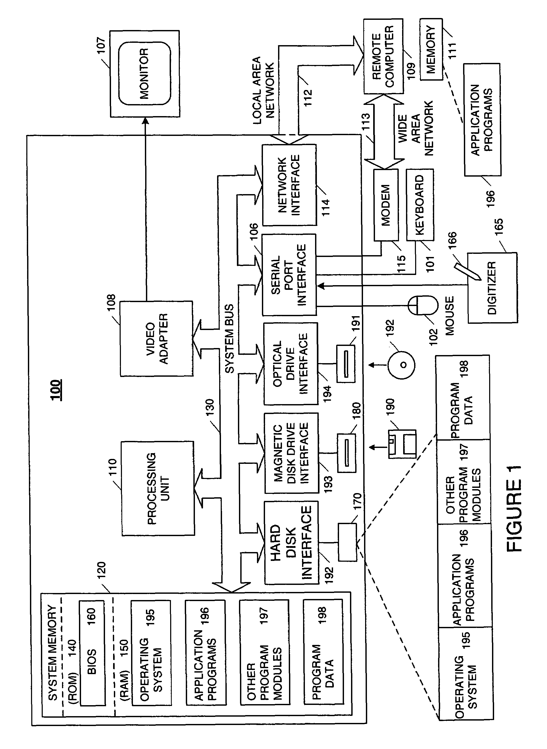
[0017]The following description is divided into sub-sections to assist the reader. The subsections include Overview; Illustrative Host Operating Environment; Charging System Environment; Illustrative Data Structure; Illustrative Operating Environment; and Alternative Charging Systems.

Overview

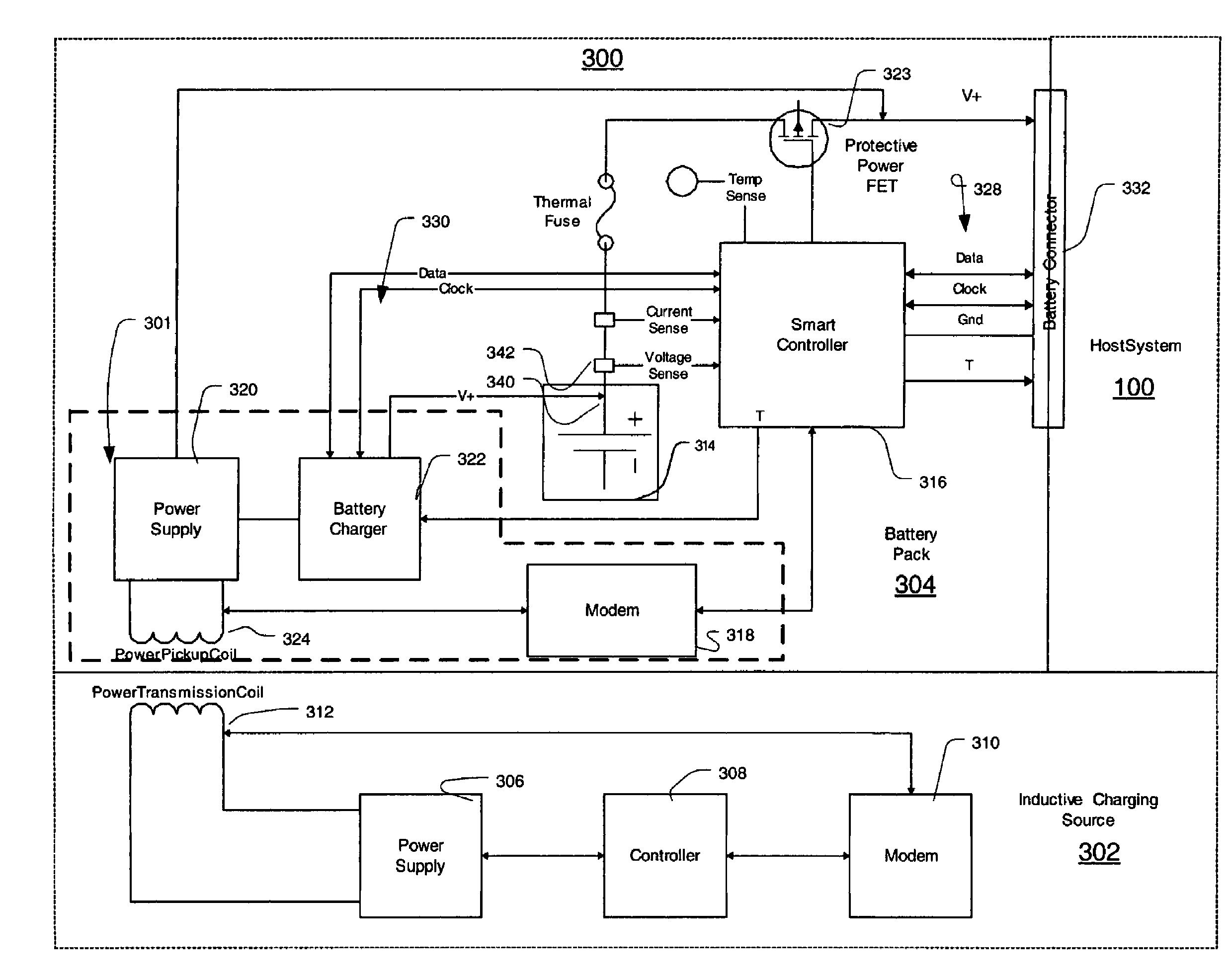
[0018]Aspects of the present invention provide inductive charging solutions enabling user convenience in wireless power environments for mobile computing and communications devices. An inductive charging system transfers energy by inductively coupling a source coil on a charging source to a receiver coil on a charging portion of a battery pack. Current flows through the source coil and the resulting magnetic flux induces an alternating current through the magnetic field and across the receiver coil, completing an energy transfer circuit. The source AC current is received in the battery pack and converted to direct current for storage in an energy storage unit of the battery pack. Aspects of the ...


PUM


Abstract

An inductive charging systems transfers energy by inductively coupling a source coil on a charging source to a receiver coil on a charging portion of a battery pack. The source current is received in the battery pack and converted to direct current for storage in the battery pack cells. Communication between a charging source and the charging portion is provided. A wireless communication arrangement provides for authentication of devices that are allowed by a source to be charged.

Description

CROSS-REFERENCE TO RELATED APPLICATIONS[0001]The present application is related to application Ser. No. 10 / 733,850, entitled “Inductive Power Adapter,” and filed on Dec. 12, 2003; which is related to application Ser. No. 10 / 733,820, entitled “Inductive Battery Charger,” and filed on Dec. 12, 2003, each of which is incorporated by reference herein as to their entireties.FIELD OF THE INVENTION[0002]Aspects of the present invention relate to battery packs for electronic apparatus. More particularly, aspects of the present invention relate to an inductively charged battery pack for electronic apparatus.BACKGROUND OF THE INVENTION[0003]Computer systems have become increasingly popular in modern society. Conventional computer systems, especially computer systems using graphical user interface (GUI) systems, accept user input from a conventional input device, such as a keyboard for entering text, and a pointing device, such as a mouse for operating the graphical user interface. The process...

Claims


Application Information

Patent Timeline
Patent Type & Authority Patents(United States)
IPC IPC(8): H02J7/00G06F1/26G06F21/00H02J7/02
CPCG06F1/26G06F21/81H02J7/025G06F2221/2129H02J7/00045H02J50/80H02J50/10
Inventor CALHOON, JOHN CHARLESKEELY, LEROY B.MITCHELL, WILLIAM
Owner MICROSOFT TECH LICENSING LLC
Learn More