
Surgical knives for large, self-sealing corneal incisions coupled to a universal intraocular lens (IOL) injector

a corneal incision and injector technology, applied in the field of surgical knives for corneal incisions coupled to universal intraocular lens injectors, can solve the problems of corneal incisions that need sutures to close, time-consuming sutures use, unavoidable astigmatism or blurry vision, etc., to achieve efficient lens space, prevent accidental movement, and improve control and safety

Inactive Publication Date: 2008-05-20
SCHOSSAU TOM M
View PDF12 Cites 53 Cited by
  • Summary
  • Abstract
  • Description
  • Claims
  • Application Information

AI Technical Summary

Benefits of technology

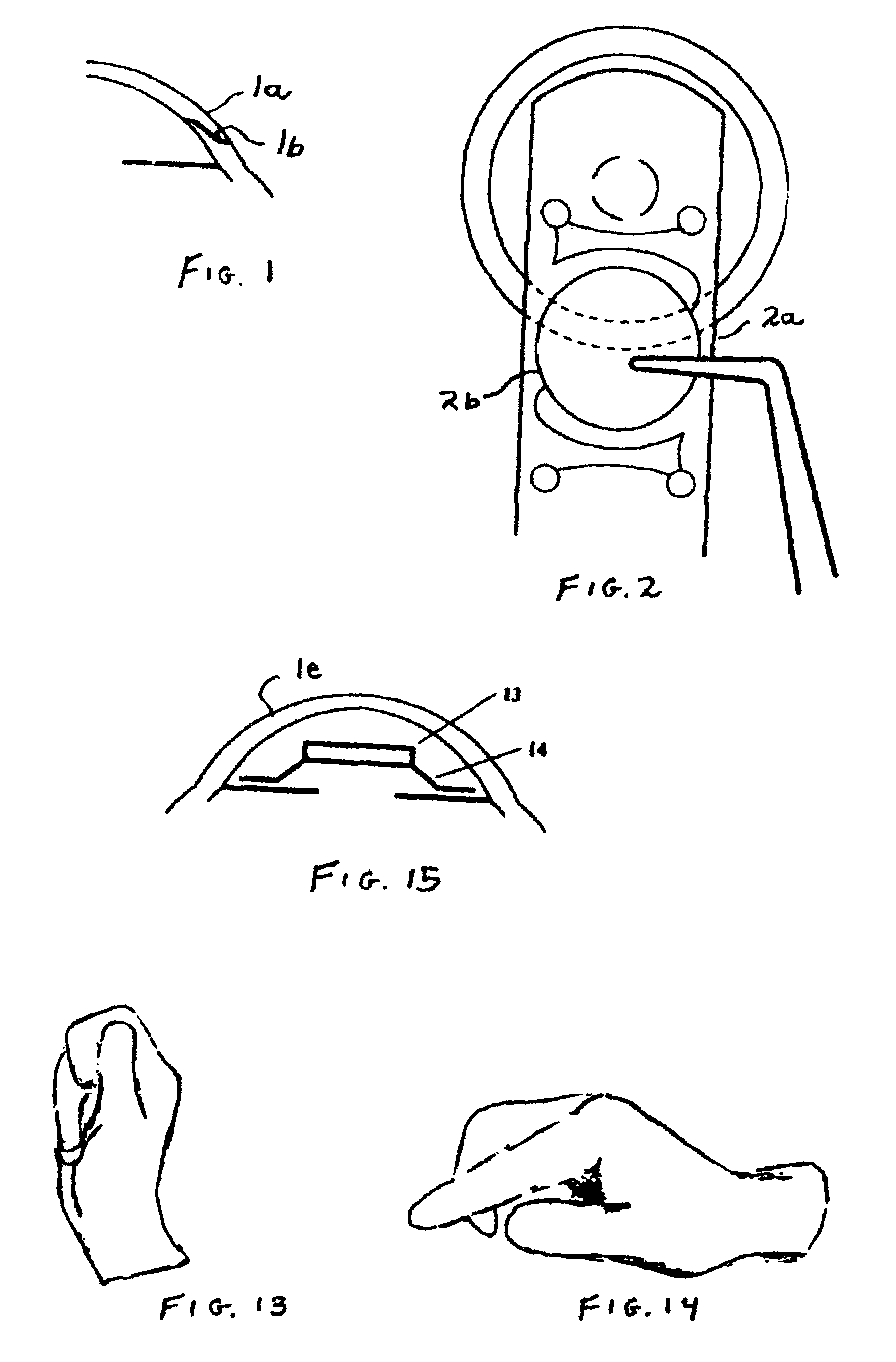
[0010]As shown in FIG. 11, the three-component intra-ocular lens (IOL) Injector system includes (a) a keratome wedge shaped knife 1 for creating the self-sealing incision in the cornea of the eye, (b) a lens glide member 10“piggy-backed” on the knife, which glide member maintains a wedge-shaped opening in the cornea, and (c) an inserter member or plunger 20 that pushes the lens into the eye, the latter two components being part of the injector device 35. The intra-ocular lens injector device 35 attaches directly to the wedge-shaped keratome knife blade so that, as soon as the incision is made in the cornea, the surgeon can replace the blade with the injector device in one motion.
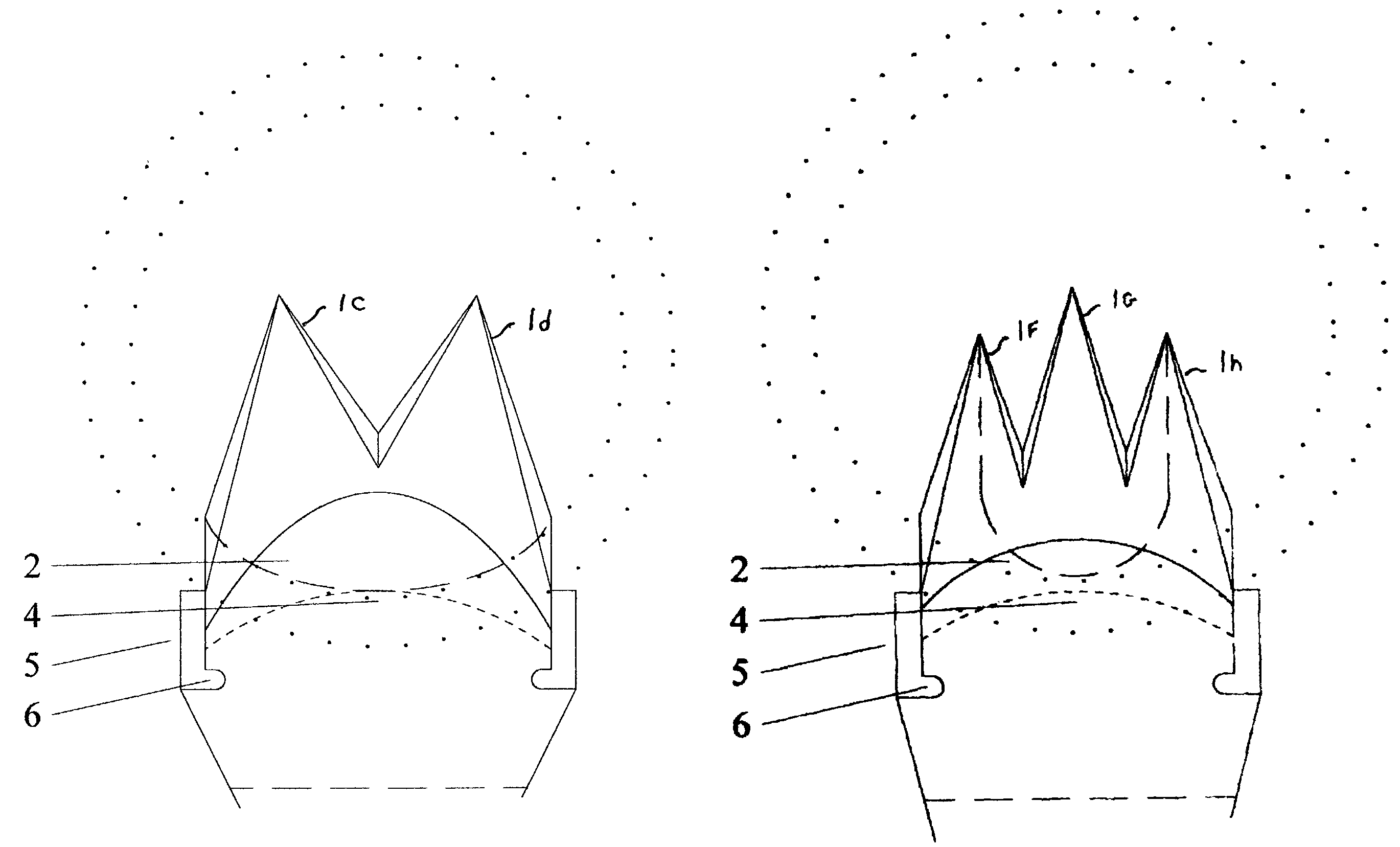
[0012]The blade 1 is wedge-shaped and has a “scooped-out” valley in the heel of the blade face, to allow the tip of the lens glide to also be inserted into the eye along with the blade. Stops 5 on the blades provide better control and safety, preventing accidental movement by the patient or surgeon that may cause harm. These stops also serve as a channel on the face of the blade to contain the lens glide. The lens glide member, in contrast with the Praeger patent, has wedge-shaped sidewalls 11 on top to wedge open the incision from above, and to channel or guide the lens 13 into the eye during insertion. This lens glide member is shaped like a boat underneath to efficiently provide room for the lens, while providing structural support and helping to open the incision from below. The lens glide member is also ergonomically designed to provide greater control and comfort for either a right- or left-handed surgeon, and for either a one- or two-handed procedure. A ball-like collar 27 on the keratome handle, much like designs currently used for writing pens, also provides for greater control by and comfort of the surgeon.

Problems solved by technology

One drawback to the Phakic IOL solution is the need for sutures to close a large incision in the cornea after implantation of a (nonfoldable) lens.
Use of sutures is time-consuming and usually causes unavoidable astigmatism or blurry vision.
However, current Phakic IOL implantation procedures necessitate larger 7-mm incisions.
Using currently available instruments to create these larger incisions requires an inefficient process of making multiple strokes, and using multiple instruments, and the results have not yet been proven to be self-sealing.
At this time there are very few instruments designed to handle the larger-sized, (nonfoldable) Phakic IOLs, and no type of a device for injecting this type of lens or a variety of lens is available.
However, current Phakic IOL implantation procedures necessitate larger 7-mm incisions.
The fact that astigmatism results from the use of sutures is nearly unavoidable (Koch).

Method used


Image

  • Surgical knives for large, self-sealing corneal incisions coupled to a universal intraocular lens (IOL) injector
  • Surgical knives for large, self-sealing corneal incisions coupled to a universal intraocular lens (IOL) injector
  • Surgical knives for large, self-sealing corneal incisions coupled to a universal intraocular lens (IOL) injector

Examples


Embodiment Construction

[0010]As shown in FIG. 11, the three-component intra-ocular lens (IOL) Injector system includes (a) a keratome wedge shaped knife 1 for creating the self-sealing incision in the cornea of the eye, (b) a lens glide member 10“piggy-backed” on the knife, which glide member maintains a wedge-shaped opening in the cornea, and (c) an inserter member or plunger 20 that pushes the lens into the eye, the latter two components being part of the injector device 35. The intra-ocular lens injector device 35 attaches directly to the wedge-shaped keratome knife blade so that, as soon as the incision is made in the cornea, the surgeon can replace the blade with the injector device in one motion.

[0011]The surgeon places the lens upon a protective plastic sheet of the lens glide member that has side walls on it; these side walls 11 act as rails and guide the lens 13 unimpeded through the incision when the surgeon pushes on a plunger or inserter member 20 within the injector device. Once the lens is c...


PUM


Abstract

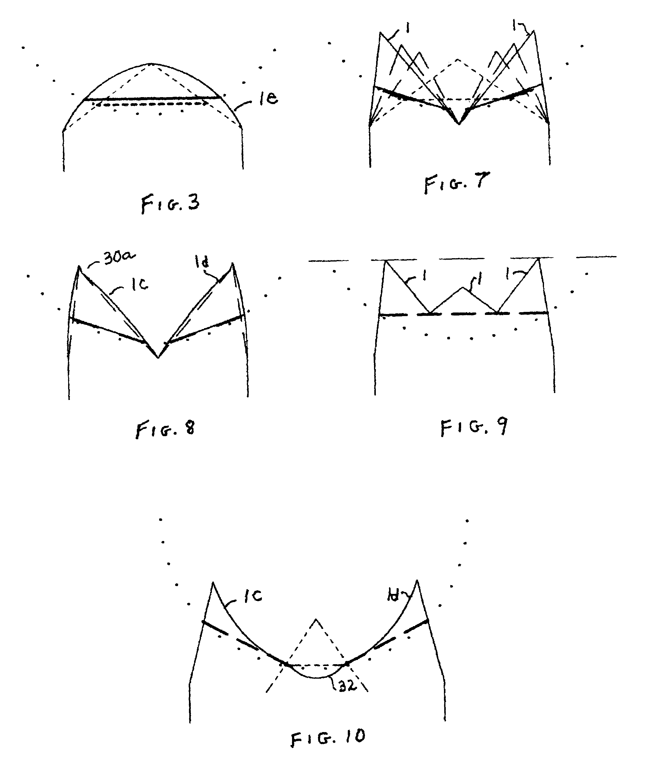
A lens injector includes a thin sheet-like lens glide member, mounted upon a tapered knife, that maintains a wedge-shaped opening in the cornea upon withdrawal of the knife. The lens is thereafter advanced under the cornea by a plunger in the injector that maintains the lens in place as the injector device is removed. A multiple point blade knife may simultaneously make a set of several small, connected incisions. The fact that each blade has only a limited depth means that the resulting wide incision can be created without the need to penetrate deeply into the cornea, as would be necessary with a single-point blade of the desired width. This is especially beneficial for creating Z-shaped incisions, which become self-sealing when internal pressure pushes the inner layer against the outer layer. This shortens the process significantly, which then results in less trauma to the eye and streamlines the entire procedure.

Description

BACKGROUND OF THE INVENTION[0001]Implantation of lenses (Phakic intraocular lenses, or PIOLs) inside normal or phakic eyes to correct vision, while retaining the ability to focus up close, has been gaining favor and popularity. Recent improvements in the quality of the IOL and the discovery by many patients that they do not qualify for laser surgery on the cornea [such as LASIK (laser-assisted in situ keratomileusis), LASEK (laser epithelial keratomileusis), or PRK (Photo Refractive Keratectomy)] mean that Phakic IOLs are increasingly in demand. In addition, it is becoming apparent that individuals qualified for both laser surgery and IOL implantation who require higher powers of correction are generally more satisfied with the Phakic IOL procedure, because it results in better quality of vision. One drawback to the Phakic IOL solution is the need for sutures to close a large incision in the cornea after implantation of a (nonfoldable) lens. Use of sutures is time-consuming and usua...

Claims


Application Information

Patent Timeline
Patent Type & Authority Patents(United States)
IPC IPC(8): A61F9/007
CPCA61F9/0133
Inventor SCHOSSAU, TOM M.
Owner SCHOSSAU TOM M
Learn More