
Power connector

a power connector and connector technology, applied in the direction of coupling contact members, fixed connections, coupling device connections, etc., can solve the problems of affecting the heat dissipation ability, and limiting the use of power connectors

Inactive Publication Date: 2008-05-20
FCI AMERICAS TECH LLC
View PDF90 Cites 61 Cited by
  • Summary
  • Abstract
  • Description
  • Claims
  • Application Information

AI Technical Summary

Benefits of technology

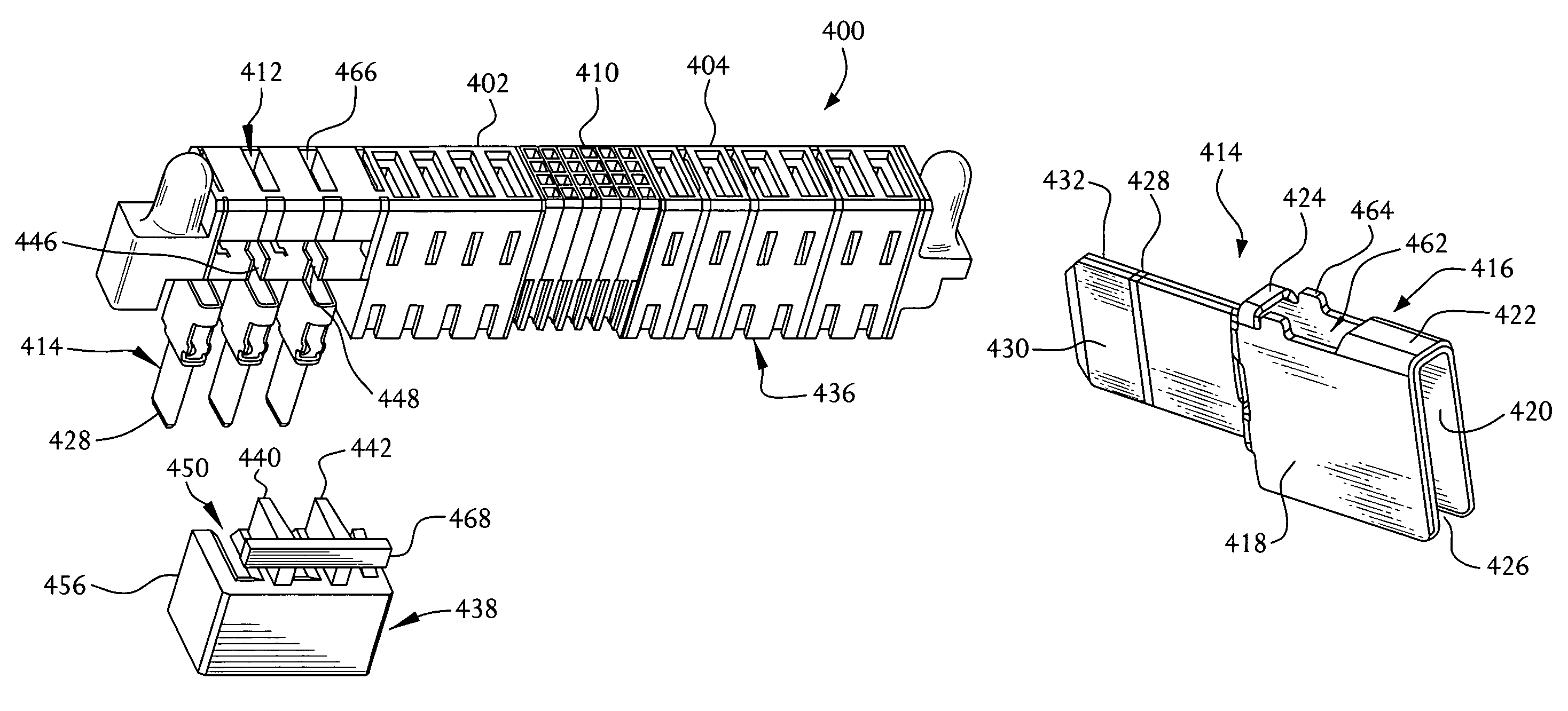
"The present invention is about electrical connectors that have a receptacle with a housing and conductive contacts. The contacts have a \"dual mass\" design that increases surface area for heat dissipation. When mated with a plug, airflow paths are created through the contacts. The invention also describes an electrical power connector that combines AC power cable connections with other power connector contacts in a single housing. This eliminates the need for a separate AC power supply. The housing can accommodate different forms of AC power supply termination contacts."

Problems solved by technology

Such arrangements are difficult to reduce in size without adversely effecting heat dissipation capabilities.
They also provide only minimal flexibility to change contact normal forces by adjustment of contact geometry.
This poses known drawbacks due to the fact that in those circumstances where the AC power supply is on the order of 30 amps or more an undesirable level of heat buildup on the traces of the power board can occur.
Also, where stand-alone cable connections are used to adapt AC power by direct wire termination onto the power distribution boards there is an additional level of complexity in the connective configurations on the board.

Method used


Image

  • Power connector
  • Power connector
  • Power connector

Examples


Embodiment Construction

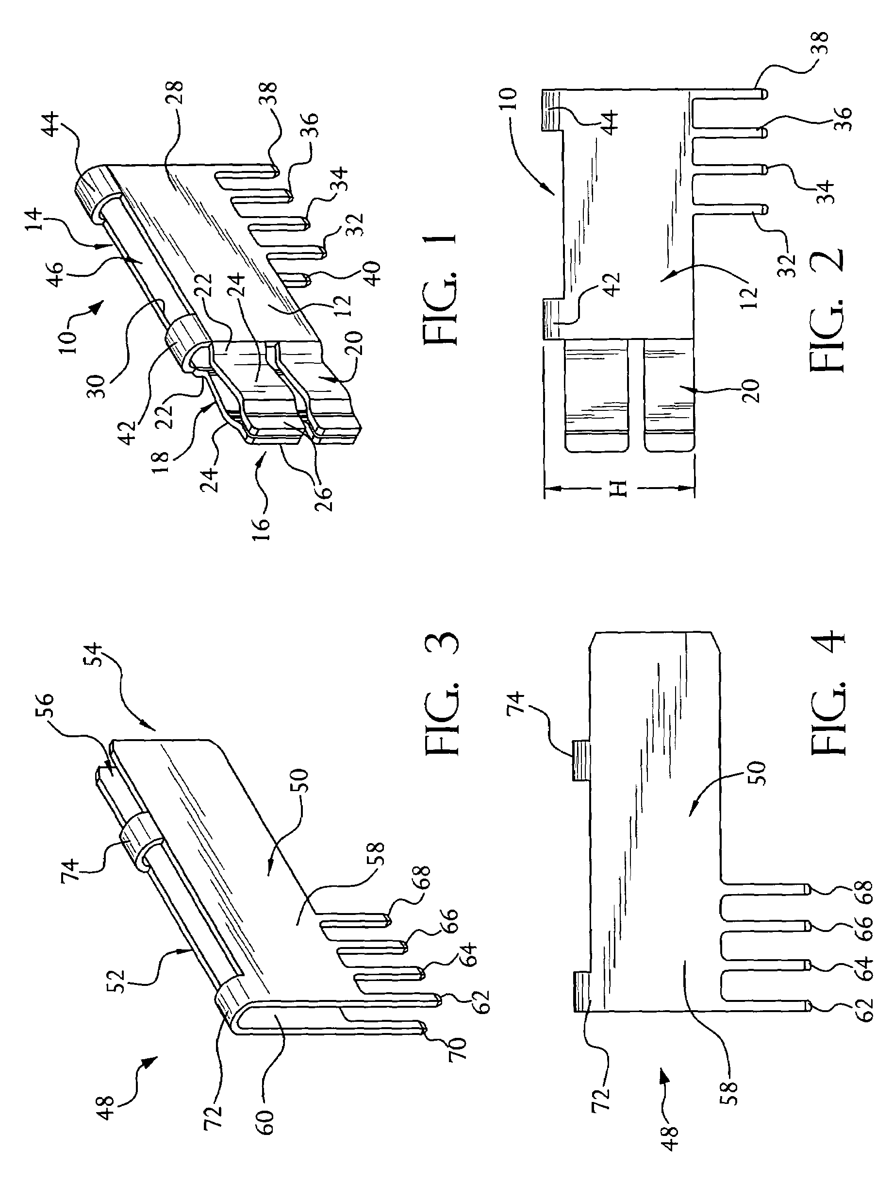
[0053]Referring to FIGS. 1 and 2, a plug contact 10 for use in a plug connector is shown. This plug contact has two opposed major side walls 12 and 14. A front projection, identified generally by numeral 16, has an upper section 18 and a lower section 20. Each of these upper and lower sections comprises a pair of opposed cantilever beams, each beam having inwardly converging proximal section 22, arcuate contact section 24 and a distal section 26. The opposed distal sections 26 are preferably parallel to each other. The distal sections can be positioned slightly apart when the beams are in relaxed condition, but come together when the beams are deflected as the front projection is inserted into a receptacle contact (as explained below). This provides over-stress protection for the beams during mating. The side walls also include planar panels 28 and 30. Terminals 32, 34, 36 and 38 extend from an edge of panel 28. Terminal 40 extends from panel 30, along with a plurality of like termi...


PUM


Abstract

A pair of mating connectors includes a receptacle having an insulative housing and at least one conductive receptacle contact with a pair of spaced walls forming a plug contact receiving space. The plug connector has an insulative housing and at least one conductive contact having a pair of spaced walls which converge to form a projection engageable in the plug receiving space of the receptacle contact. The electronic power connectors can also be modified to accommodate connections for an external AC power supply. The connector housing incorporating the AC power connection capability can accommodate different forms of AC power supply termination contacts, such as spade-type contacts having a spring-like plug for receiving discrete quick connect socket terminals.

Description

CROSS REFERENCE TO RELATED APPLICATIONS[0001]This is a continuation of U.S. application Ser. No. 09 / 944,266, filed on Aug. 31, 2001, now abandoned, which is a continuation-in-part of U.S. application Ser. No. 09 / 160,900, filed on Sep. 25, 1998, now U.S. Pat. No. 6,319,075, which claims the benefit of Provisional Application No. 60 / 082,091, filed Apr. 17, 1998, the contents of all of which are incorporated by reference herein.FIELD OF THE INVENTION[0002]The present invention relates to electrical connectors and more particularly to electronic power connectors especially useful in circuit board or backplane interconnection systems.BACKGROUND OF THE INVENTION[0003]Designers of electronic circuits generally are concerned with two basic circuit portions, the logic or signal portion and the power portion. In designing logic circuits, the designer usually does not have to take into account any changes in electrical properties, such as resistance of circuit components, that are brought abou...

Claims


Application Information

Patent Timeline
Patent Type & Authority Patents(United States)
IPC IPC(8): H01R12/00H01R11/22H01R12/50H01R12/70H01R12/72H01R13/05H01R13/10H01R13/533H01R24/00H01R31/06H01R107/00H05K1/00
CPCH01R13/055H01R13/10H01R12/727H01R12/7088H01R23/7073Y10S439/949Y10S439/947H01R12/724H01R11/22
Inventor SCHELL, MARK S.TREECE, EDWARDDAILY, CHRISTOPHER
Owner FCI AMERICAS TECH LLC
Learn More