
System and method for improved control of tooth movement with elastic repositioning appliances

a technology of elastic repositioning and control device, applied in the field of realignment of teeth, can solve the problems of less control of force generated by prior art elastic repositioning device, less control of polymeric shell or tooth positioner, and less importance of rotation error to achieve desired effect, etc., to achieve better tooth alignment and straightening, improve control of tooth movement, and enhance the quality of treatment outcome

Inactive Publication Date: 2008-05-20
SOLOMON FREDERICK
View PDF62 Cites 27 Cited by
  • Summary
  • Abstract
  • Description
  • Claims
  • Application Information

AI Technical Summary

Benefits of technology

"This patent describes a method for improving the control of tooth movement during orthodontic treatment. The method uses elastic repositioning appliances, such as polymeric shells or a preprogrammed series of shells, to move teeth into their proper position. The invention recognizes that these appliances rely upon a force transverse across a tooth, facial to lingual or lingual to facial, and that single forces applied to the crown of a tooth induce a rotational moment that must be controlled. The invention provides a computer aided finite element analysis to predict the path of movement and accurately models the actual force application. The invention also incorporates micro-regional force application and perimetrical force placement to improve the control of tooth movement. Overall, the invention improves the quality of orthodontic treatment by increasing the clinical control of the treating dentist."

Problems solved by technology

The forces generated by prior art elastic repositioning appliances, polymeric shells or tooth positioners are less controlled due to the difficulty in creating precise couples as a result of the imprecise location, magnitude and direction of the forces they generate.
The preceding patents have the problem of controlling the tooth rotations created upon all axes generated by the unwanted moments induced by the imprecise forces applied to the teeth.
These rotations and forces create unwanted side effects including deviating from the intended treatment path or plan.
With early generations of these elastic repositioning appliances, movement was limited to one or two simple stages and the error introduced by rotation was of little importance to achieving the desired outcome.
When the appliance is installed, the poor fit of the appliance distorts its shape, which creates an orthodontic force as it tries to return to its shape.
This decrease in orthodontic force can limit the intended movement, as the force drops below an effective therapeutic level before reaching the target transitional tooth position.
This shortfall, as a result of inadequate force, though of little significance in a short sequence of appliances, may accumulate in a longer series of appliances thus deviating from the intended treatment path.
Controlling the rotational moment of the orthodontic force inherent in prior art flexible-positioning appliances that cause tooth rotation away from the intended treatment becomes more difficult by the cumulative effect of successive appliances, e.g. if each appliance creates a 2° unintended rotation, then over ten appliances the effect grows to 20°.
A minor problem with one or two appliances now introduces a major error when applied over a greater number of appliances.
However, common computer modeling in the absence of increased control of forces permits unwanted deviation from a narrow treatment path.
Once the attachment loosens unintended, unfavorable forces may arise and the options to recapture the tooth dwindle.
Controlling unwanted rotation with attachments also faces unfavorable physics.
When using elastic repositioning appliances or tooth positioners in the form of polymeric shells, the predictable forces generated by the distortion of the appliance act buccally and lingually. FIG. 5B illustrates a poorly fit polymeric shell when placed over a tooth to be rotated, because the appliance cannot distort efficiently in a mesial or distal direction, the attachment will not fit into its concavity.
In consequence, the above described deviations from the intended treatment path may cause the remaining appliances to have marginal effect or become unusable.
Modifications to the prior art appliances is extremely limited.
Reconfiguration of the appliance sequence to remedy the new, though unintended, tooth position calls for new impressions of the patient's teeth and expensive and lengthy rework of the appliance sequence.

Method used


Image

  • System and method for improved control of tooth movement with elastic repositioning appliances
  • System and method for improved control of tooth movement with elastic repositioning appliances
  • System and method for improved control of tooth movement with elastic repositioning appliances

Examples


Embodiment Construction

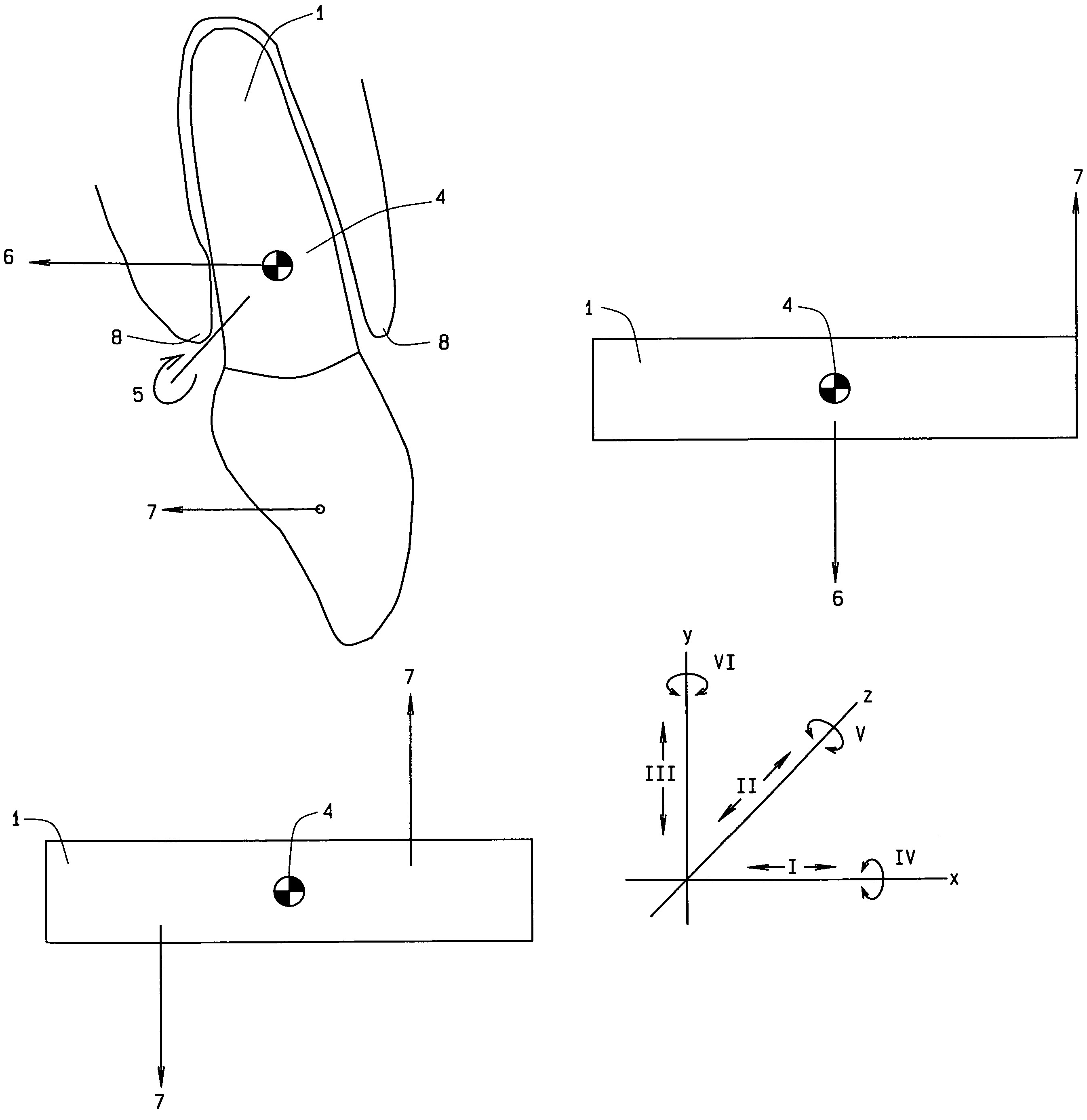
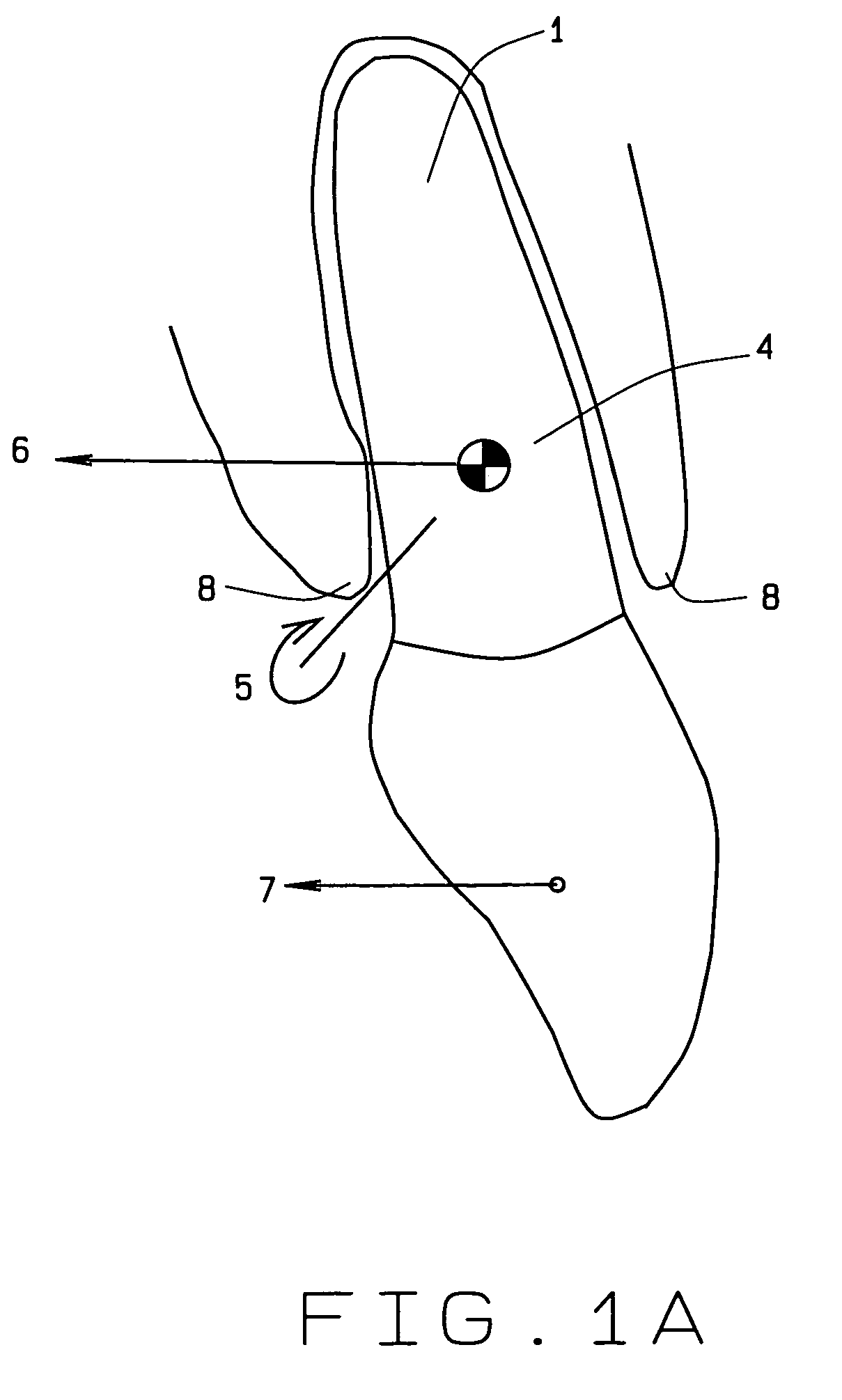
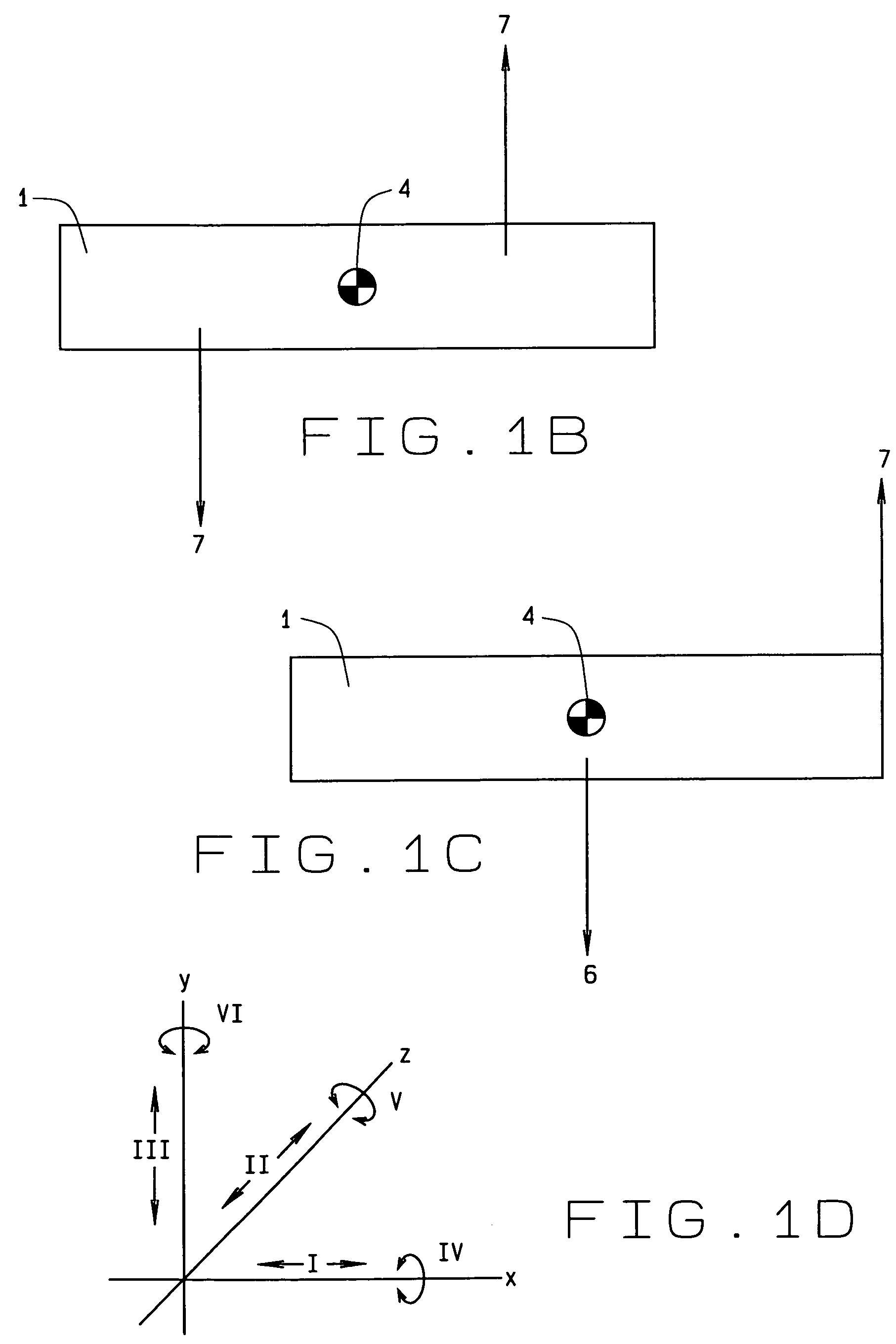
[0052]This invention improves the control of the orthodontic movement of teeth in all six degrees of freedom of movement. FIG. 1D shows the six degrees of freedom for movement of a treated tooth by utilizing the plastic repositioning appliance or the tooth positioner. Translation is shown by the x, y, z axes enumerated at i, ii, iii respectively and moment is shown by rotation about the x, y, z axes enumerated as iv, v, vi respectively. The tooth positioner of the present invention is a polymeric shell, individually, or in series.

[0053]The prior art devices provide for shifting and movement of teeth, but with limited control and unintended movement. For example in FIG. 1, the forces applied to a tooth 1 are evaluated around a point called the “center of resistance” CRes 4 which is the orthodontic equivalent of the center of mass. A single force applied at any location other than the CRes creates a rotational effect measured as a moment 5. All forces and moments applied to a tooth ar...


PUM


Abstract

Micro-regional force application improves the control of the orthodontic movement of teeth in all six degrees of freedom. Micro regional force application utilizes an elastic repositioning appliance, a tooth positioner, a polymeric shell, or preprogrammed series of polymeric shells. The key components of the invention are the envelope of freedom, the force applicators, force couplers, counterpart coupling, vector modifiers, seating guides, decouplers, and forced balance points. Further, computerized finite element analysis determines the center of resistance and the center of rotation for each tooth to be moved. The present invention gently rotates and translates one or more teeth to a desired straight position within a treatment plan.

Description

CROSS REFERENCE TO RELATED APPLICATION[0001]This non-provisional application claims priority to the provisional application for patent Ser. No. 60 / 666,908 which was filed on Mar. 31, 2005.BACKGROUND OF THE INVENTION[0002]This invention relates to realignment of teeth, and more specifically pertains to the micro-regional force applications that tighten the control of the orthodontic movement of teeth in multiple directions.[0003]The field of dentistry known as orthodontics involves applying forces to teeth in their current positions to create stresses in the periodontal ligament which connects the teeth to the supporting bone. These stresses stimulate the apposition and resorption of the supporting bone matrix allowing the teeth to be repositioned in the matrix to the position desired by the treating dentist. The direction, magnitude, range and relative positions on a tooth of the forces applied, in combination with the properties of an individual tooth to be moved, determine the act...

Claims


Application Information

Patent Timeline
Patent Type & Authority Patents(United States)
IPC IPC(8): A61C3/00
CPCA61C7/08A61C7/002
Inventor SOLOMON, FREDERICK
Owner SOLOMON FREDERICK
Learn More