
Method and apparatus for improving image quality in a reflecting telescope

a technology of reflecting telescope and image quality, which is applied in the field of telescopes, can solve the problems of reducing the image clarity of the edge of the image, affecting the image quality of the image, so as to achieve the effect of effectively and efficiently sweeping away the thermal gradient boundary layer, enhancing the image clarity, and reducing the current of the tub

Inactive Publication Date: 2008-05-20
WILLEY GERALD
View PDF6 Cites 6 Cited by
  • Summary
  • Abstract
  • Description
  • Claims
  • Application Information

AI Technical Summary

Benefits of technology

This approach allows for immediate or near-immediate use of the telescope with significantly improved image clarity, achieving thermal equilibrium within 5 to 15 minutes and minimizing distortion, even when the mirror is initially at a different temperature than the ambient air.

Problems solved by technology

Having to wait this long in order to utilize the telescope is a source of considerable frustration to astronomers and star gazers.
The problem of achieving thermal equilibrium is further exacerbated, in areas of the country where the ambient air drops significantly after sundown, such as in desert areas, where the nighttime temperature can easily drop ten to fifteen degrees in the hours after sunset.
These tube currents cause distortion of the periphery of the image.
While the approaches disclosed by Greer and Adler, to utilization of a fan for expedited cooling and management of a thermal boundary layer adjacent the concave face of a mirror provide some improvement in addressing the problems described above, inter alia, these and other prior approaches are not entirely satisfactorily, and further improvement is desirable.
For example, with the approach advocated by Adler, of mounting the fan to blow directly on the concave reflecting surface of the mirror, the fan is also blowing dust, moisture or other contaminates directly onto the reflecting surface of the mirror, thereby requiring that extreme care be taken to keep the mirror free of contamination, and that frequent, undesirable cleaning of the mirror be performed to maintain optimal performance of the telescope.
Directing air flow from a fan at or across the concave face of the mirror does little to help remove heat from the cell at an expedited rate.

Method used


Image

  • Method and apparatus for improving image quality in a reflecting telescope
  • Method and apparatus for improving image quality in a reflecting telescope
  • Method and apparatus for improving image quality in a reflecting telescope

Examples


Embodiment Construction

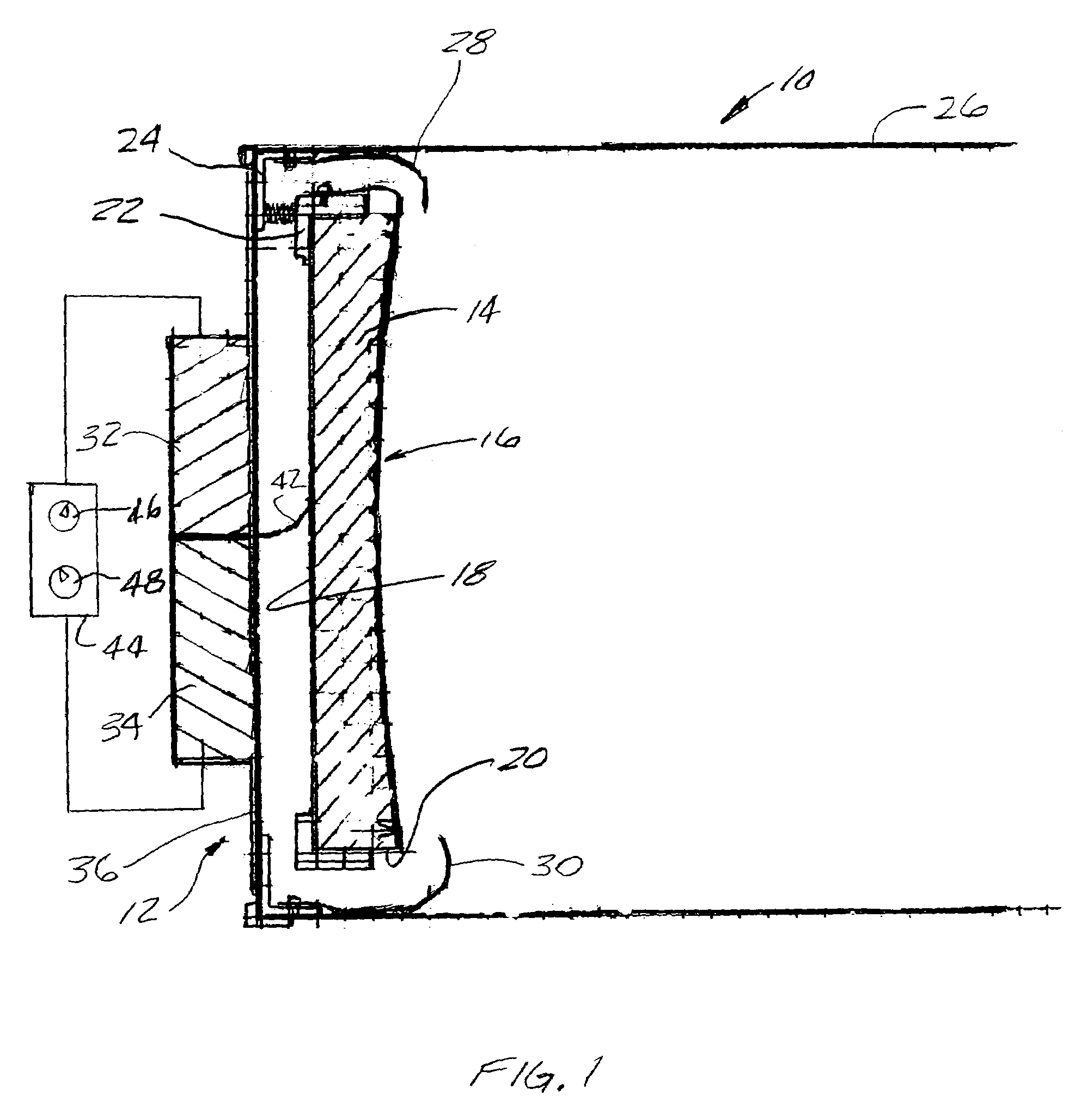
[0028]FIGS. 1-3 show a first exemplary embodiment of the invention, in the form of a reflector telescope 10, including an apparatus 12 for improving image quality in the reflector telescope 10.

[0029]As best seen in FIG. 1, the exemplary embodiment of the reflector telescope 10 includes a mirror 14 having a front concave reflecting surface 16, a backside 18, and a periphery 20. The mirror 14 is mounted in a conventional adjustable cell arrangement 22, which is in turn adjustably attached to a bottom end 24 of a tube 26 of the telescope 0O.

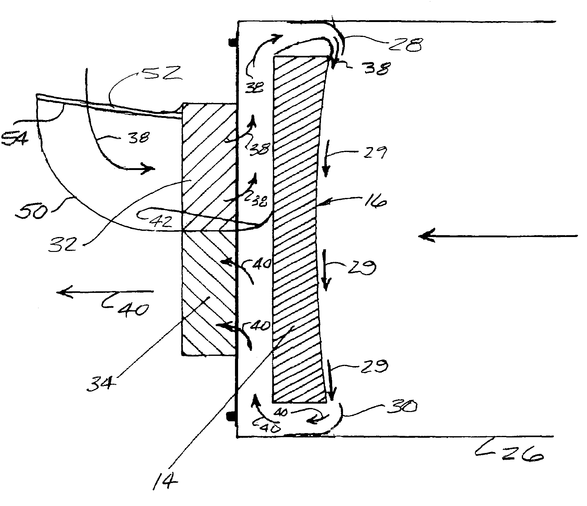
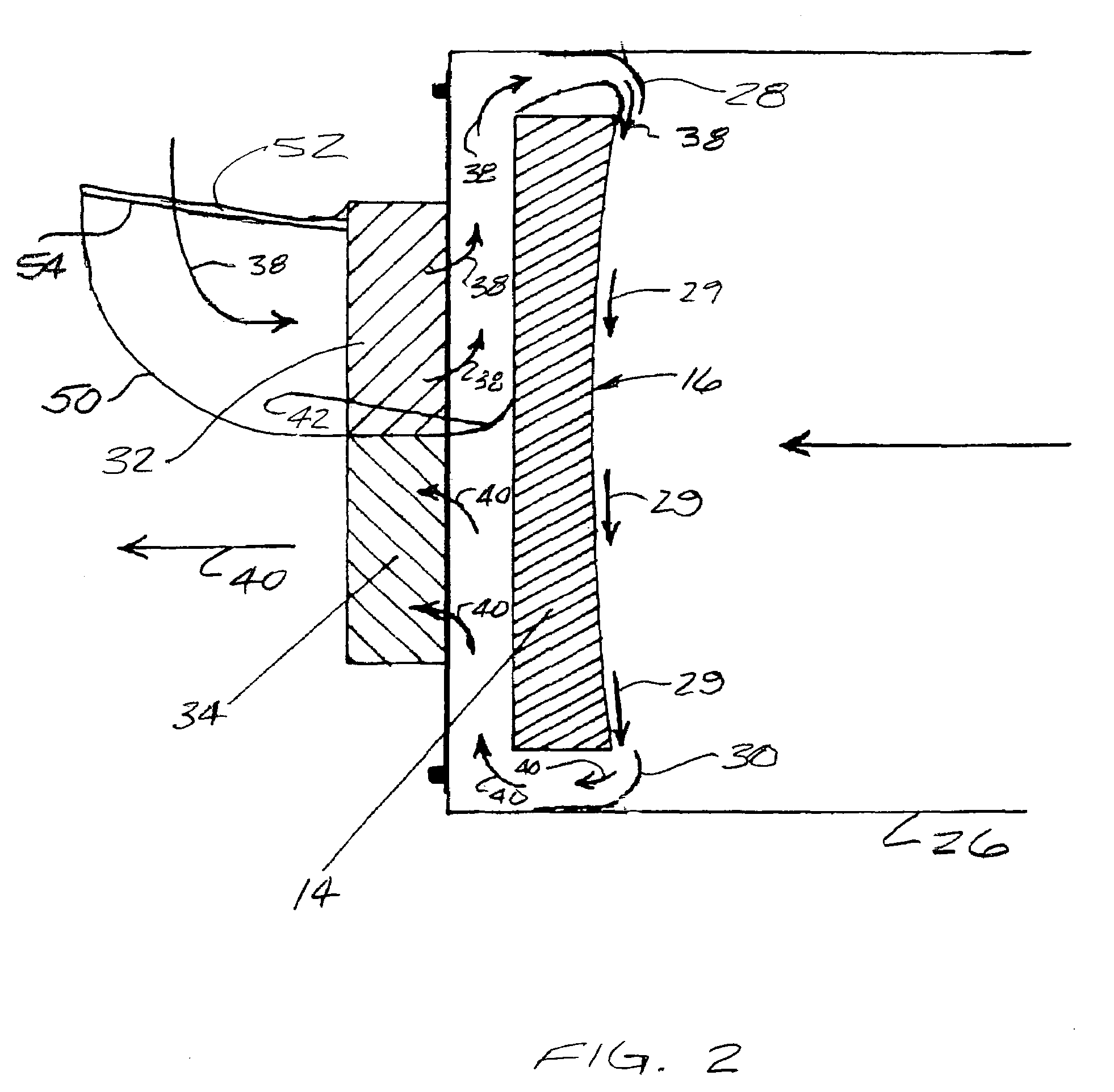
[0030]The apparatus 12 for improving image quality, in the exemplary embodiment, includes a plurality of supply nozzles 28 disposed about the periphery 20 of the mirror 14, for directing a flow of air from the backside 18 of the mirror 14 across the concave reflecting surface 16 of the mirror 14, in the manner illustrated by arrows 38 and 29 in FIG. 2.

[0031]The apparatus 12 for improving image quality, in the exemplary embodiment of the telescope 10...


PUM


Abstract

A method and apparatus for improving image quality in a reflector-type telescope are provided, through utilization of one or more nozzles disposed about the periphery of a reflecting mirror of the telescope, for directing a flow of air from a backside of the mirror across a concave reflecting surface of the mirror, to thereby sweep away and / or preclude formation of image distorting thermal boundary layers, or other impediments to image quality, resulting from the mirror not being in thermal equilibrium with ambient air surrounding the mirror. Supply nozzles are provided around a portion of the periphery of the mirror, and exhaust pick-up nozzles are provided around another portion of the periphery of the mirror, to thereby cause a flow of air to closely adhere to the concave surface of the mirror.

Description

CROSS-REFERENCE TO RELATED PATENT APPLICATIONS[0001]This patent application claims the benefit of U.S. Provisional Patent Application No. 60 / 733,027, filed Nov. 3, 2005, the disclosure and teachings of which are incorporated herein, in their entirety, by reference.FIELD OF THE INVENTION[0002]This invention relates to telescopes, and more particularly to a method and apparatus for improving image clarity of a reflecting telescope operating under conditions where a mirror of the reflecting telescope is not in thermal equilibrium with ambient air adjacent the mirror.BACKGROUND OF THE INVENTION[0003]In a typical Newtonain reflector-type telescope, a mirror, having a concave face, is located at one end of an elongated tube, or frame, and adjusted such that the concave face of the mirror will reflect and focus an image for viewing through an eyepiece axially disposed from the concave face of the mirror at an open end of the tube or frame of the telescope. By virtue of this arrangement, li...

Claims


Application Information

Patent Timeline
Patent Type & Authority Patents(United States)
IPC IPC(8): B60R1/06G02B23/00
CPCG02B7/008G02B23/06
Inventor WILLEY, GERALD
Owner WILLEY GERALD
Learn More