
Apparatus and method for coding excitation signal

a technology of excitation signal and coding apparatus, which is applied in the direction of code conversion, data switching network, instruments, etc., can solve the problems of increasing the amount of memory, the amount of calculation or the scale of a program, and the influence of an error to propagate for a long time, so as to improve the error characteristic, improve the correlation, and improve the effect of the sn ratio

Active Publication Date: 2008-05-13
III HLDG 12 LLC
View PDF7 Cites 12 Cited by
  • Summary
  • Abstract
  • Description
  • Claims
  • Application Information

AI Technical Summary

Benefits of technology

This approach effectively suppresses error propagation and improves communication quality by generating a signal with a waveform similar to the original, even if the adaptive codebook is not functioning correctly, thereby enhancing error resilience and maintaining quality under transmission errors.

Problems solved by technology

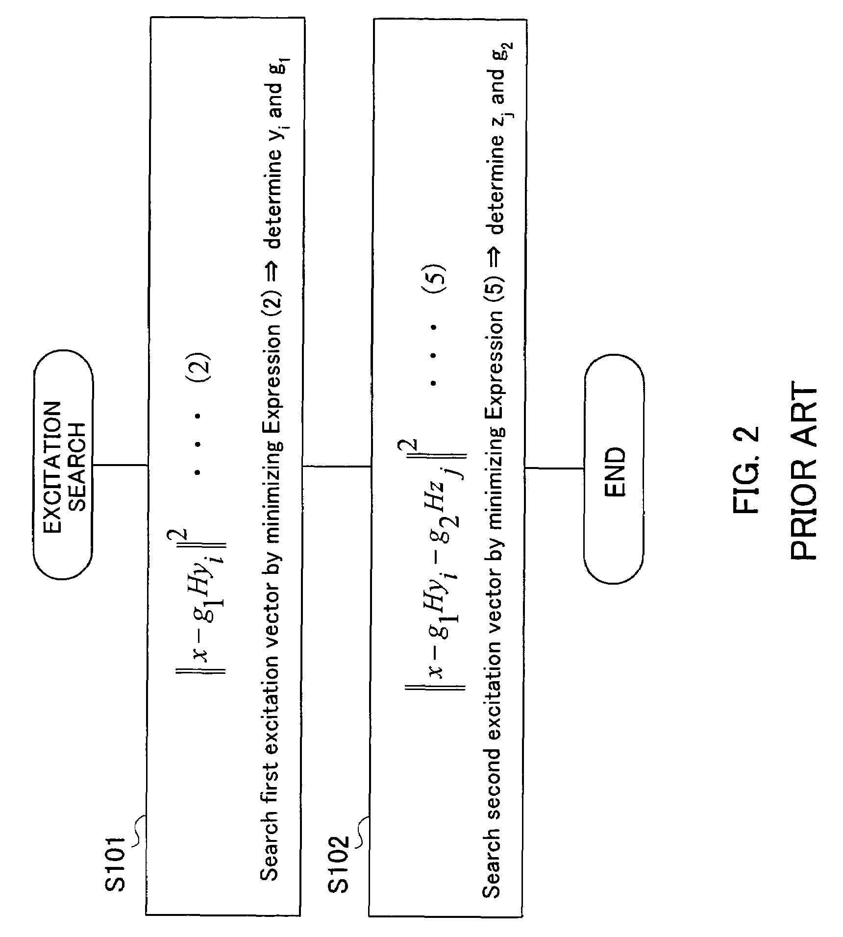
On the other hand, the second excitation vector zj is generated correctly if a correct code is received, but when a periodic signal is coded as described above, the coding (codebook search) is performed so that there is no strong correlation between the second excitation vector zi and target vector x, and therefore it is not possible to generate a signal close to the target vector x, which causes the influence of an error to be propagated for a long time.
However, changing the configuration of the adaptive codebook itself as described above may cause an amount of memory, amount of calculation or the scale of a program, etc., to increase.
Furthermore, when a specific algorithm defined by standards, etc., needs to be used, it is not possible to change the configuration of the adaptive codebook itself to improve the error characteristic as described above.
Though the technique described in Non-Patent Document 2 has no such problems, but has considerable deterioration of quality after reset and fails to achieve effects in frames which are not reset.

Method used


Image

  • Apparatus and method for coding excitation signal
  • Apparatus and method for coding excitation signal
  • Apparatus and method for coding excitation signal

Examples


Embodiment Construction

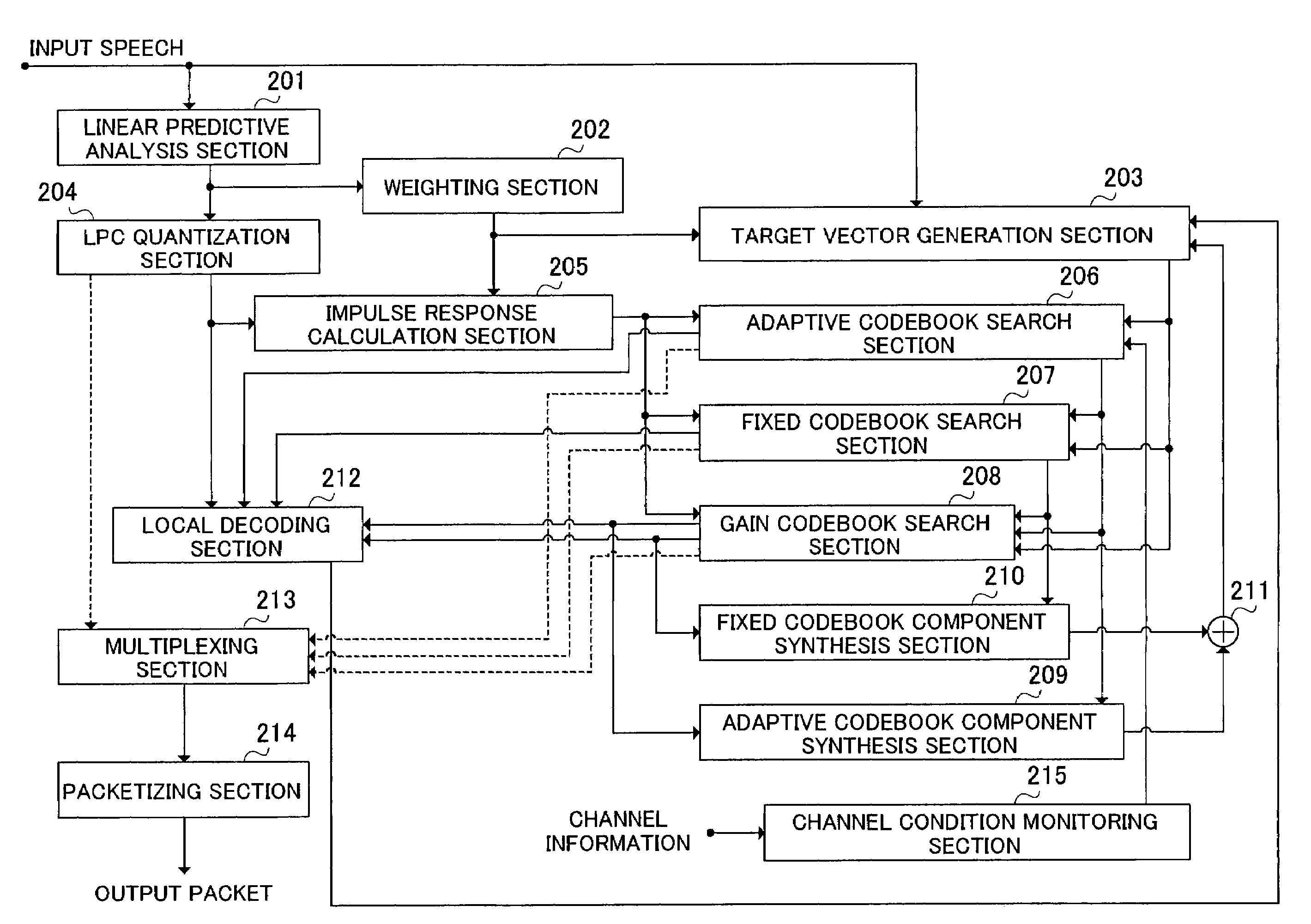
[0033]With reference now to the attached drawings, an embodiment of the present invention will be explained in detail below.

[0034]FIG. 3 is a block diagram showing a configuration of a speech signal transmission system according to an embodiment of the present invention.

[0035]In FIG. 3, the speech signal transmission system comprises a base station 100 provided with the function as an excitation signal coding apparatus of the present invention and a mobile station apparatus 110.

[0036]The base station 100 comprises an input apparatus 101, an A / D conversion apparatus 102, a speech coding apparatus 103, a signal processing apparatus 104, an RF modulation apparatus 105, a transmission apparatus 106 and an antenna 107.

[0037]An input terminal of the A / D conversion apparatus 102 is connected to the input apparatus 101. An input terminal of the speech coding apparatus 103 is connected to an output terminal of the A / D conversion apparatus 102. An input terminal of the signal processing appar...


PUM


Abstract

An excitation signal coding apparatus capable of improving an error resilience by changing an excitation vector search method (more specifically, an error minimization criterion during a search). This coding apparatus is allowed to choose either of an ordinary search method and the search method of the present invention with using information input from a transmission channel condition monitoring section (215). That is, an ordinary search method is used when the transmission channel condition is good and no packet discarding is observed on the receiving side, and the search method of the present invention is used otherwise (when packet discarding is observed on the receiving side at a discarding rate of 5% or more, for example).

Description

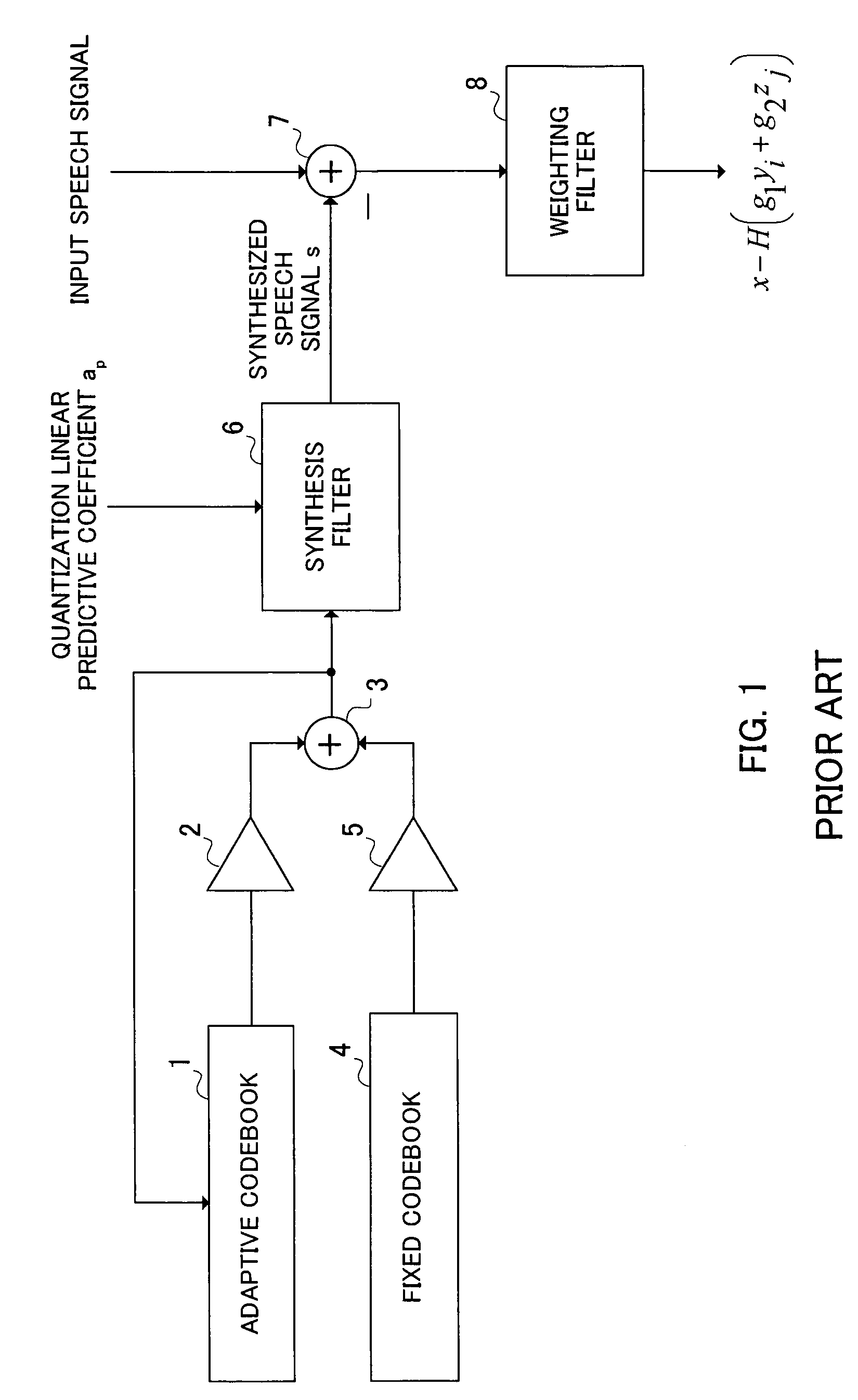
BACKGROUND OF THE INVENTION[0001]1. Field of the Invention[0002]The present invention relates to an excitation signal coding apparatus and an excitation signal coding method.[0003]2. Description of the Related Art[0004]Conventionally, a CELP (code excitation linear prediction) speech coding scheme generally uses, as an excitation coding means, a configuration provided with two types of excitation codebooks; a codebook whose contents are adaptively changed based on past output and a codebook with predetermined fixed contents, excitation signals being coded with the sum of vectors output from these two types of codebooks.[0005]More specifically, it is a general practice that an adaptive codebook which is a buffer of coding excitation vectors generated in the past is used as the codebook of the former and an algebraic codebook, noise codebook or random codebook, etc., is used as the codebook of the latter. Here, the codebook of the former will be referred to as an “adaptive codebook” a...

Claims


Application Information

Patent Timeline
Patent Type & Authority Patents(United States)
IPC IPC(8): G10L15/20G10L19/06G10L19/08G10L19/09H03M7/30H04B14/04H04L1/00H04L12/56H04W24/00H04W28/04
CPCG10L19/22H04L1/0014H04L1/0015H04W24/00H04W28/04G10L2019/0013
Inventor EHARA, HIROYUKI
Owner III HLDG 12 LLC
Learn More