
Low-ripple optical device

a technology of optical devices and low-ripple, which is applied in the field of optical communication, can solve the problems of demultiplexers oftentimes exhibiting significant ripples in the passband, and achieve the effect of straightforward manufacturing

Inactive Publication Date: 2008-05-13
LUCENT TECH INC
View PDF4 Cites 0 Cited by
  • Summary
  • Abstract
  • Description
  • Claims
  • Application Information

AI Technical Summary

Benefits of technology

[0005]As can be appreciated, the concatenation of the two substantially cancels out any individual ripple, thereby making systems constructed from the device themselves capable of being cascaded.
[0006]Viewed from yet another advantageous aspect of the present invention, the device is relatively straightforward to manufacture using planar lightwave methodologies and materials.

Problems solved by technology

When implemented as planar lightwave circuits, however demultiplexers oftentimes exhibit a passband having significant ripple.
This is due to a trade-off made between ripple and sidewall steepness inherent to filter design.

Method used


Image

  • Low-ripple optical device
  • Low-ripple optical device
  • Low-ripple optical device

Examples


Embodiment Construction

[0012]The following merely illustrates the principles of the invention. It will thus be appreciated that those skilled in the art will be able to devise various arrangements which, although not explicitly described or shown herein, embody the principles of the invention and are included within its spirit and scope.

[0013]Furthermore, all examples and conditional language recited herein are principally intended expressly to be only for pedagogical purposes to aid the reader in understanding the principles of the invention and the concepts contributed by the inventor(s) to furthering the art, and are to be construed as being without limitation to such specifically recited examples and conditions.

[0014]Moreover, all statements herein reciting principles, aspects, and embodiments of the invention, as well as specific examples thereof, are intended to encompass both structural and functional equivalents thereof. Additionally, it is intended that such equivalents include both currently kno...


PUM


Abstract

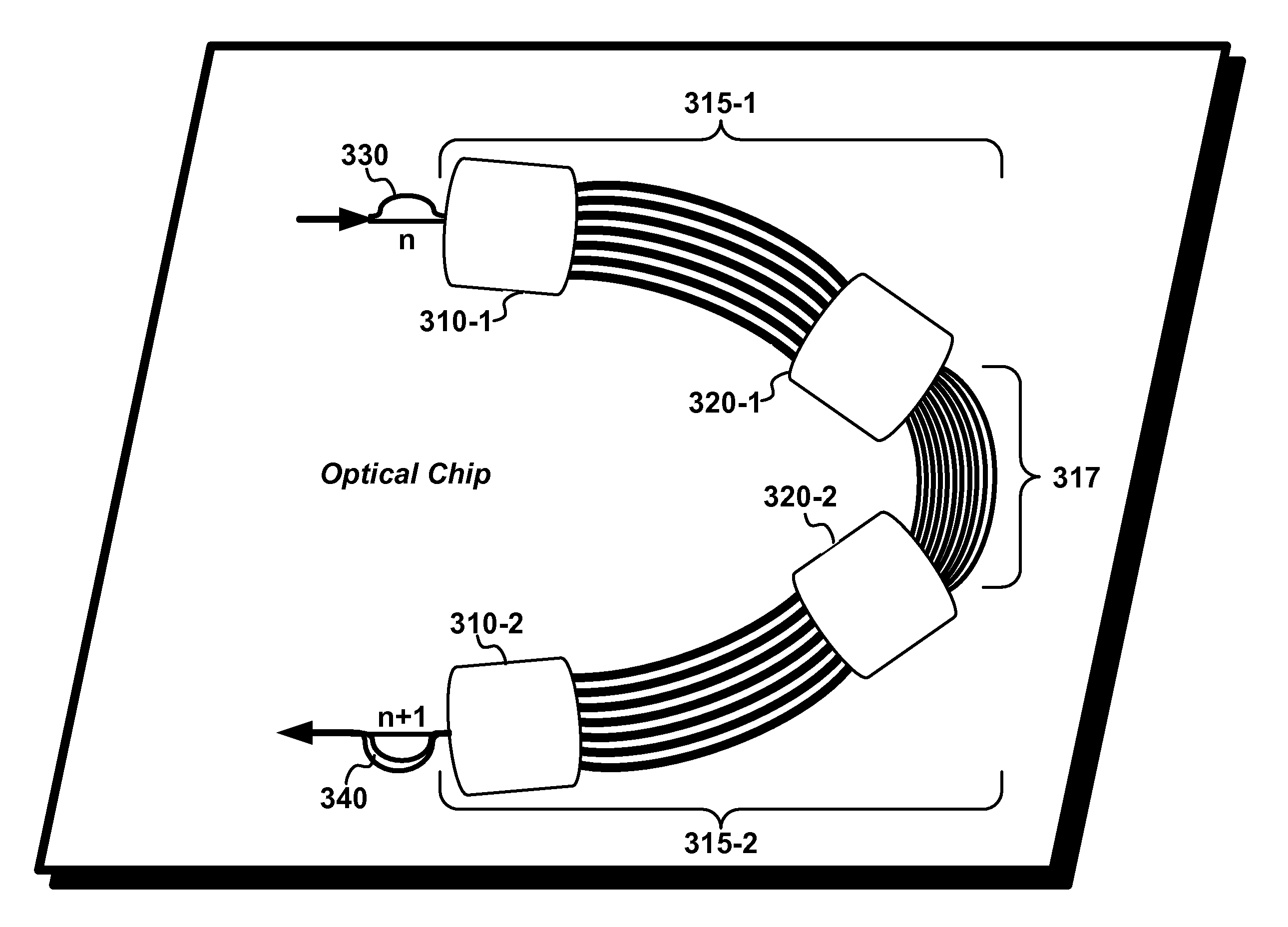
A low-ripple optical device comprising an optical demultiplexer structure and an optical multiplexer structure cascaded together wherein one of the structures exhibits n passband maxima and the other device exhibits n+1 passband maxima.

Description

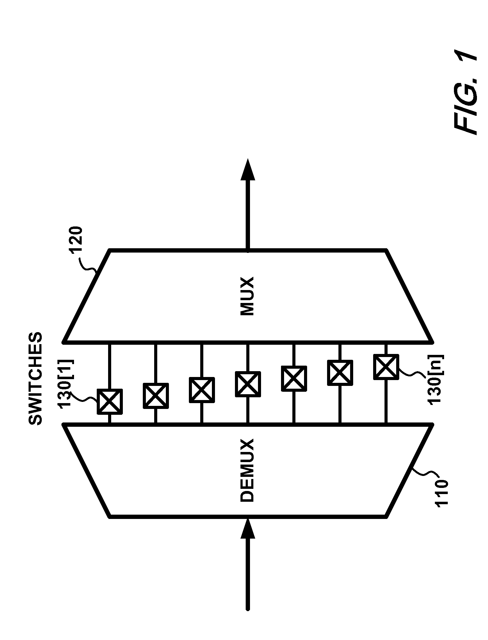
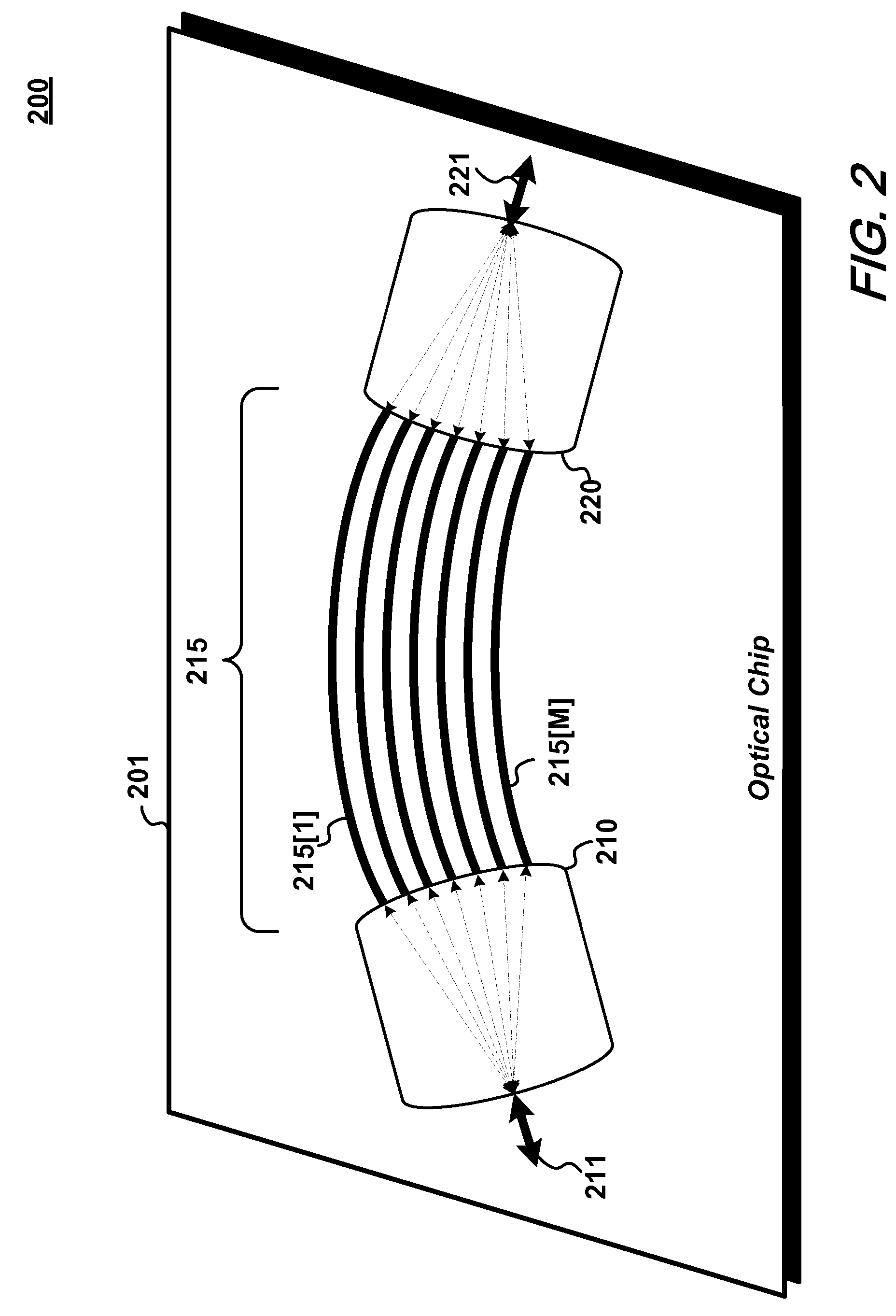
FIELD OF THE INVENTION[0001]This invention relates generally to the field optical communications and in particular to a low-ripple optical device for use in wavelength-division-multiplexed (WDM) optical networks.BACKGROUND OF THE INVENTION[0002]Present day optical communications networks employ a great number of optical multiplexers and demultiplexers. When implemented as planar lightwave circuits, however demultiplexers oftentimes exhibit a passband having significant ripple. This is due to a trade-off made between ripple and sidewall steepness inherent to filter design.SUMMARY OF THE INVENTION[0003]I have developed—according to the present invention—a low ripple optical device comprising a demultiplexer and a multiplexer concatenated together wherein the demultiplexer exhibits n passband maxima while the multiplexer exhibits n+1 passband maxima.[0004]Viewed from a first aspect, the multiplexer may exhibit an odd number of passband maxima while the demultiplexer may exhibit an even...

Claims


Application Information

Patent Timeline
Patent Type & Authority Patents(United States)
IPC IPC(8): G02B6/28H04J14/02H04B10/2581
CPCG02B6/12021H04J14/02G02B6/356H04J14/0307H04B10/2581
Inventor DOERR, CHRISTOPHER
Owner LUCENT TECH INC
Learn More