
Loudspeaker driver

a loudspeaker and driver technology, applied in the direction of diaphragm construction, electromechanical transducer, transducer diaphragm, etc., can solve the problems of shortening the life of the diaphragm, increasing distortion, and affecting the operation of the loudspeaker, so as to reduce the moment of action

Active Publication Date: 2008-05-13
GOOGLE LLC
View PDF31 Cites 22 Cited by
  • Summary
  • Abstract
  • Description
  • Claims
  • Application Information

AI Technical Summary

Benefits of technology

[0018]wherein the suspension acts in a plane generally passing through the centre of mass of the massive member, thereby reducing any moment acting on the suspension.
[0019]As a result of this latter feature, the exciter may have dynamic balance, and suspension drift or creep under the force of gravity for a vertical placement may be alleviated.
[0025]Such an arrangement provides the vibration transfer benefits of a non-repeatedly engageable connection—such as adhesive—to the loudspeaker panel together with ease of replaceability of the exciter unit associated with a repeatedly-engageable, releasable connection, such as a screw thread.

Problems solved by technology

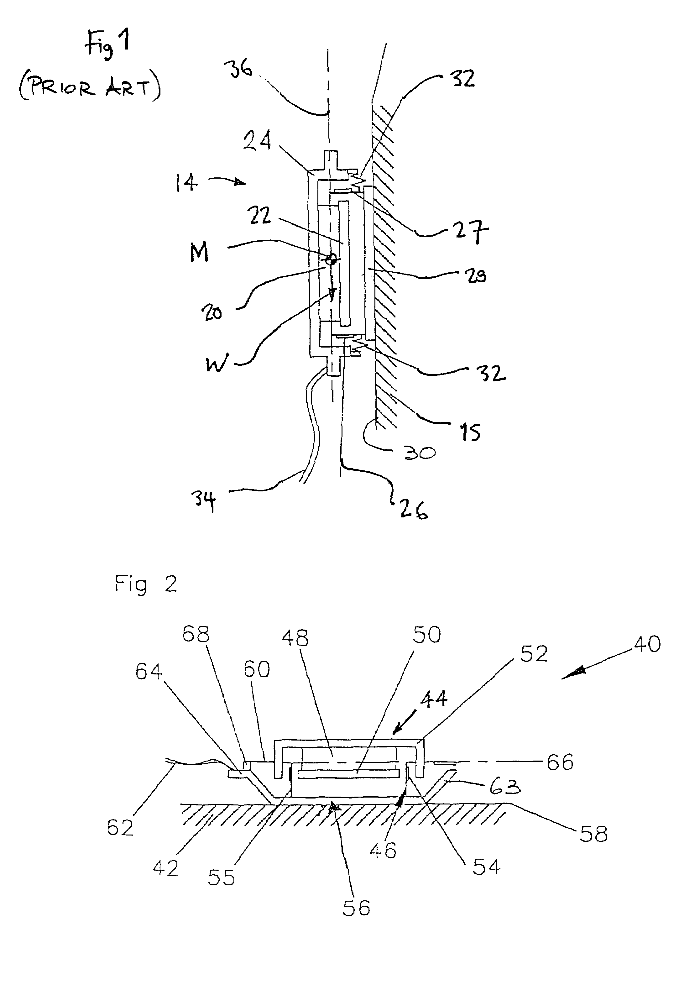
Firstly, when installed on a non-horizontal panel as shown in FIG. 1, the exciter tends to “creep”, i.e. twist on its suspension under the effect of the weight, W, of the magnet assembly acting through its centre of mass, M. Secondly, the exciter may exhibit rocking modes which degrade power handling, shorten life, and increase distortion.
In particular, leakage of energy into rocking modes may impair the power delivery at the lowest frequencies.
Further issues surround the mounting of the exciter as a whole.
However, should an exciter attached in this manner develop a fault, it will be necessary to break the adhesive joint and remove adhesive residue from the surface of the loudspeaker panel before a replacement exciter can be attached by means of a new adhesive bond.

Method used


Image

  • Loudspeaker driver
  • Loudspeaker driver
  • Loudspeaker driver

Examples


Embodiment Construction

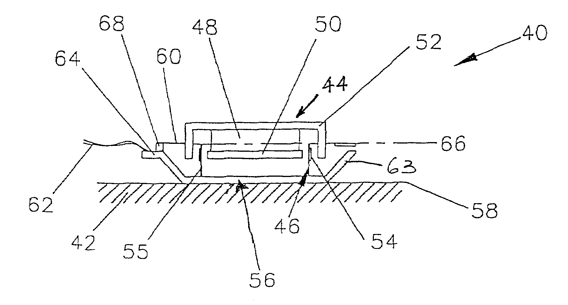
[0035]FIG. 1 shows a known prior art exciter 14 and is described in detail above. As is shown in FIG. 1, the suspension 32 is spaced away from the plane of centre of mass 36 of the magnet assembly 20,22,24.

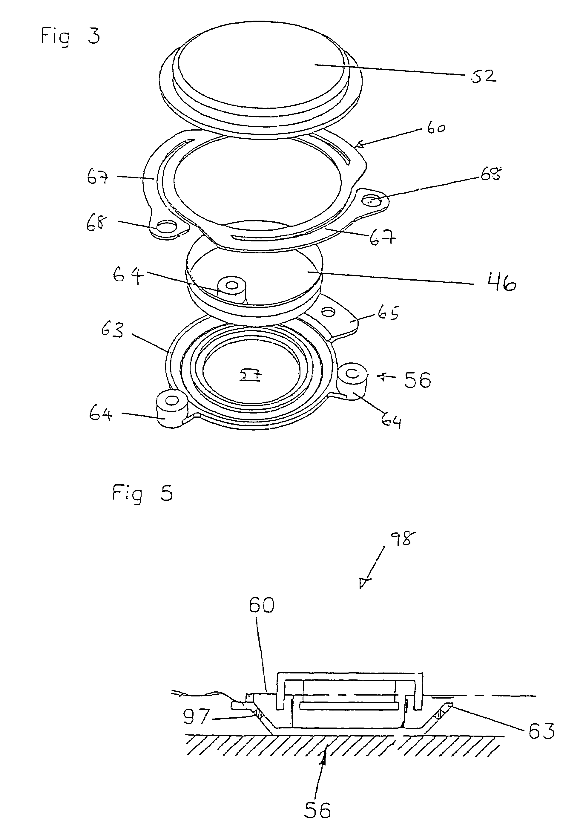
[0036]FIGS. 2 and 3 show an exciter 40 according to the present invention. In FIG. 2, the exciter 40 is mounted on an acoustic radiator 42 and comprises an electromagnetic motor made up of a magnet assembly 44 and a voice coil assembly 46. The magnet assembly 44 comprises a magnet 48, a pole piece 50 and a magnet cup 52 such that the magnet 48 is sandwiched between and attached to both the pole piece 50 and the magnet cup 52. The voice coil assembly 46 comprises a voice coil 54 wound on a former 55 which is attached to a coupler 56.

[0037]The voice coil assembly 46 of the exciter 40 is attached to the acoustic radiator 42 via the coupler 56 mounted on a mounting surface 58 of the acoustic radiator 42. The magnet assembly 44 is mounted adjacent the voice coil assembly 46 by means of...


PUM


Abstract

An inertial exciter (40) for an acoustic radiator (42), and a loudspeaker incorporating an acoustic radiator and such an exciter. The exciter has a massive member (44); a coupler (56) adapted for attachment to the acoustic radiator (42) and adapted for relative movement with respect to the massive member (44); a motor for effecting relative movement of the coupler with respect to the massive member; and a suspension (60) for supporting the massive member relative to the coupler. The suspension (60) acts in a plane generally passing through the center of mass of the massive member, thereby reducing any moment acting on the suspension.Also disclosed is a loudspeaker exciter assembly (70) that has a base plate (86) for attachment to an acoustic radiator in a non-repeatedly engageable manner, and an exciter (40) attached to the base plate (86) in a repeatedly engageable manner; and a loudspeaker incorporating such an exciter assembly.

Description

[0001]This application claims the benefit of provisional application No. 60 / 247,967, filed Nov. 14, 2000.FIELD OF THE INVENTION[0002]This invention relates to drivers or exciters for loudspeakers, in particular but not exclusively for the class of loudspeakers known as bending wave panel-form loudspeakers.BACKGROUND ART[0003]Such loudspeakers are known, for example, from international application WO97 / 09842, and counterpart U.S. application Ser. No. 08 / 707,012, filed Sep. 3, 1996, both to New Transducers Ltd. In general, such speakers include a resonant bending wave acoustic radiator, e.g. in the form of a plate, and a transducer mounted on the plate to convert electrical signals into mechanical vibrations. The transducer excites the resonant bending wave modes in the plate, which then emits sound to create an acoustic output.[0004]The properties of the acoustic radiator may be chosen to distribute the resonant bending wave modes substantially evenly in frequency. In other words, th...

Claims


Application Information

Patent Timeline
Patent Type & Authority Patents(United States)
IPC IPC(8): H04R25/00H04R7/04H04R9/06H04R11/02
CPCH04R9/066H04R7/045
Inventor BUOS, ANDREASCOLLOMS, MARTIN
Owner GOOGLE LLC
Learn More