
Varistor body and varistor

a varistor and body technology, applied in the direction of varistor cores, current responsive resistors, varistortors, etc., can solve the problems of difficult suppression of plating extension and plating adhesion, inability to fully prevent inability to fully suppress etc., to achieve suppressing plating extension and plating adhesion, small composition uniformity, and significant reduction of plating extension and plating adh

Active Publication Date: 2008-05-13
TDK CORPARATION
View PDF6 Cites 7 Cited by
  • Summary
  • Abstract
  • Description
  • Claims
  • Application Information

AI Technical Summary

Benefits of technology

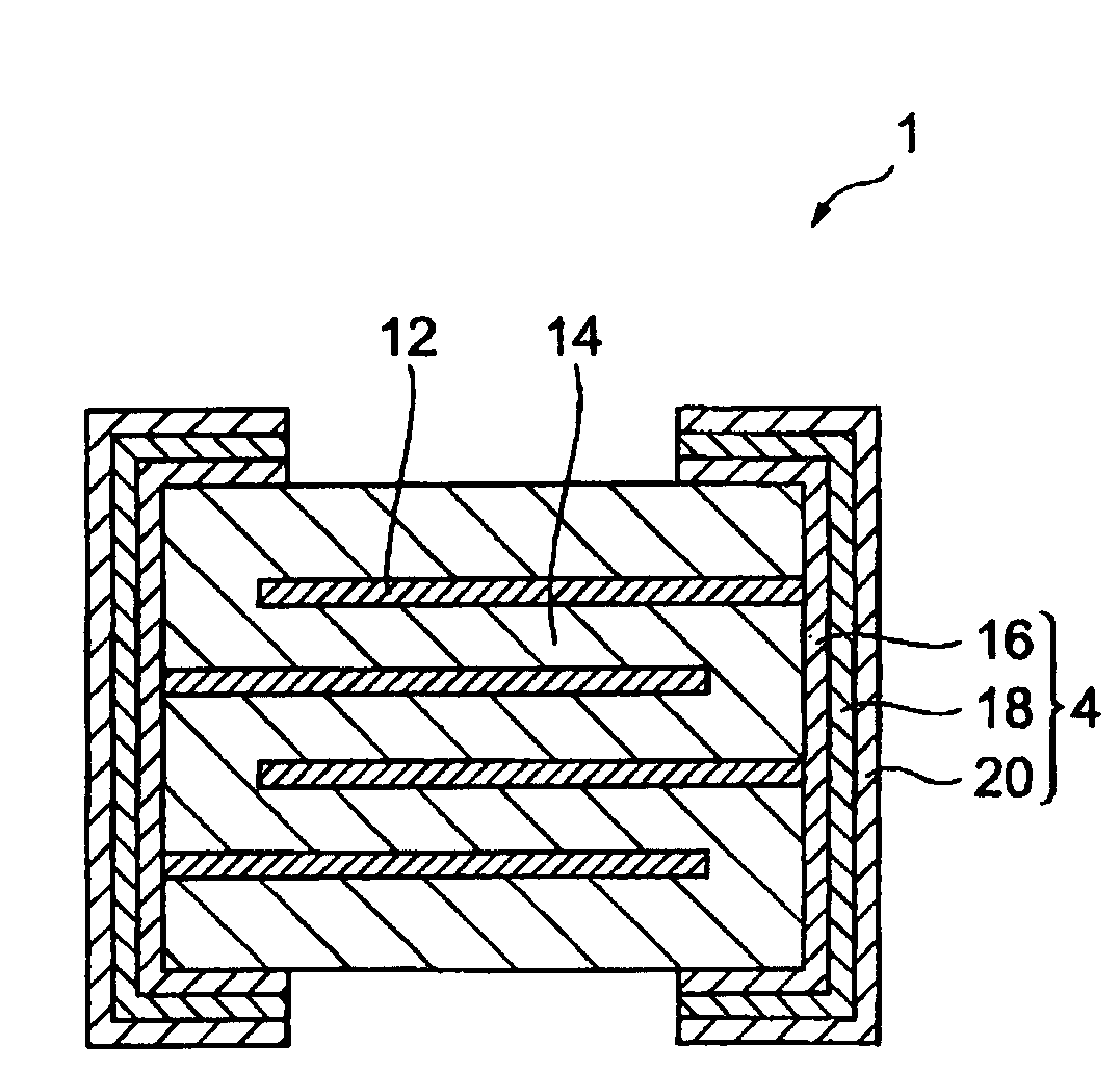
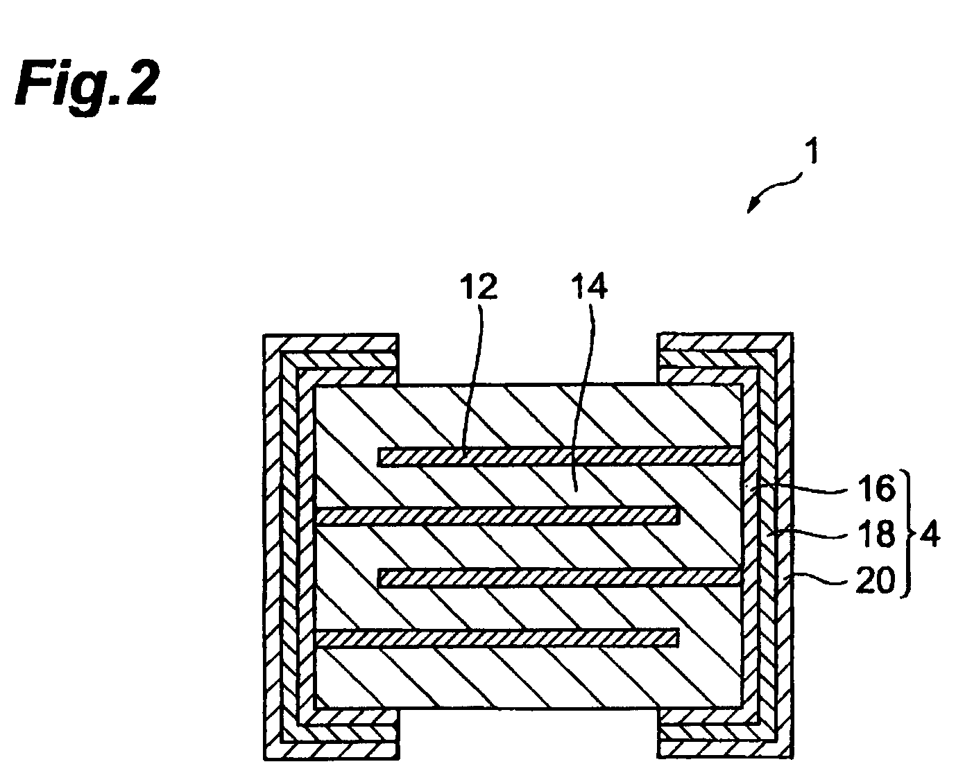
[0016]According to the above varistor body, even when a substrate electrode is formed and a plating is formed thereon, the plating extension and the plating adhesion significantly decrease. Although the causes of the phenomenon are not fully analyzed, a presumable reason is as follows. Since a non-uniformity of composition and a local difference of resistance in a region near the surface act as nuclei for forming plating, they likely become the cause of plating extension and plating adhesion. On the other hand, the varistor body according to the present invention contains auxiliary components (Pr, Zr), which specifically likely become the cause of non-uniformity of composition and local difference of resistance in the vicinity of the surface, so as to satisfy the above specific conditions. As a result, the varistor body according to the present invention shows small non-uniformity of composition and local difference of resistance in a region near the surface, thus suppressing the plating extension and the plating adhesion. As described above, during plating, elution and etching on the surface of the varistor body may probably proceed simultaneously. The varistor body of the present invention, however, has small non-uniformity of composition and local difference of resistance in a region near the surface, thus the elution and the etching can favorably be controlled. Also with the phenomenon, the plating extension and the plating adhesion can considerably be decreased.

Problems solved by technology

There are, however, cases that the countermeasure disclosed in Japanese Patent Application Laid-Open No. 9-246017 cannot fully prevent the plating extension and plating adhesion during plating.
In particular, when Li or Na is to diffuse into a deep region, there is a tendency of difficult to suppress the plating extension and plating adhesion.
That is, since the composition of the region in the vicinity of the surface of the varistor body is not homogeneous, the resistance in the vicinity of the surface of varistor body shows non-uniform distribution, which causes the plating extension and plating adhesion.
With a varistor body having a non-homogeneous composition in the vicinity of the surface thereof, however, uniform etching and elution are difficult to attain, which also becomes a cause of the plating extension and plating adhesion.
Even with that high resistance varistor body, however, the non-homogeneity issue of composition in the vicinity of the surface thereof cannot fully be solved, and it is difficult to fully suppress the plating extension and plating adhesion.

Method used


Image

  • Varistor body and varistor
  • Varistor body and varistor
  • Varistor body and varistor

Examples


manufacture example 1

[0054]The firing was conducted by total 14 hours of treatment containing the steps of heating the varistor body to 1200° C. at a heating rate of 200° C. / hr, of holding the varistor body at the temperature of 1200° C. for 2 hours, and of cooling the varistor body at a cooling rate of 200° C. / hr. The annealing was conducted under the conditions of heating the varistor body to 850° C. in 20 minutes, holding the varistor body at the temperature of 850° C. for 20 minutes, and then cooling the varistor body to the original temperature in 20 minutes.

manufacture example 2

[0055]The firing and the annealing were given under the same condition as that of Manufacture Example 1. However, instead of the method of Li diffusion to the varistor body by annealing after adhering of the Li compound in the barrel treatment, Manufacture Example 2 conducted the Li diffusion in gas phase not by the method of adding the Li compound in the barrel treatment but by the method of coexistence of Li2CO3 in the furnace in the annealing.

manufacture example 3

[0056]The firing was conducted by total 13 hours of treatment containing the steps of heating the varistor body to 1200° C. at a heating rate of 200° C. / hr, of holding the varistor body at the temperature of 1200° C. for 1 hour, and of cooling the varistor body at a cooling rate of 200° C. / hr. The annealing was conducted under the conditions of heating the varistor body to 850° C. in 20 minutes, holding the varistor body at the temperature of 850° C. for 20 minutes, and then cooling the varistor body to the original temperature in 20 minutes. Furthermore, Manufacture Example 3 conducted the Li diffusion in the varistor body by the same method as that in Manufacture Example 2.

[Determination of P1 / P0 and Z1 / Z0]

[0057]Each ten samples of varistor body were taken from each group of varistor bodies in Manufacture Examples 1 to 3, (ten samples collected from each manufacture example were numbered to “Samples Nos. 1 to 10). On the portion of varistor layer exposed on the surface of each of ...


PUM


Abstract

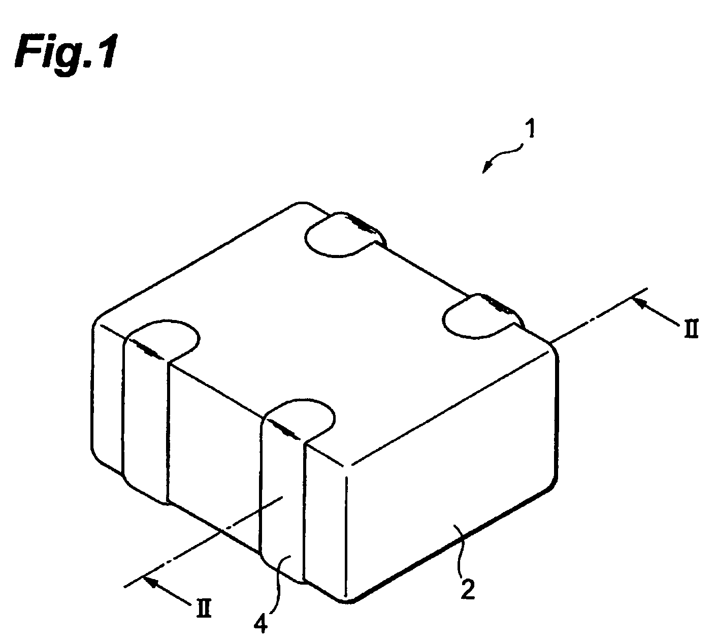
A preferred varistor body 2 has a structure of alternately laminated internal electrode layer 12 and varistor layer 14. The varistor layer 14 has a composition containing ZnO as the main component, and Co, Pr, and Zr as the auxiliary components. An analysis of the varistor body 2 in the depth direction from the surface thereof satisfies the formula (1) and (2):0.4×Z1 / Z0+0.5≦P1 / P0≦0.4×Z1 / Z0+0.9  (1)1<Z1 / Z0<2.2  (2)where, Z0 is the Zr content at a reference depth where the Zr content becomes almost constant, Z1 is the Zr content at a level of 2 μm at the surface side above the reference depth, P0 is the Pr content at the reference depth, and P1 is the Pr content at a level of 2μm at the surface side above the reference depth.

Description

BACKGROUND OF INVENTION[0001]1. Field of the Invention[0002]The present invention relates to a varistor body and a varistor having the same.[0003]2. Related Background Art[0004]Varistor is an element showing a voltage nonlinear characteristic which keeps insulation property with high resistance up to a certain voltage, and dramatically becomes a low resistance above that certain voltage to allow current to flow therethrough, (hereinafter referred to as the “varistor characteristic”). Utilizing the characteristic, the varistor is used as an element for protecting a circuit of electronics device in case of generation of abnormal voltage (surge), and the like. In recent years, the varistor has become miniature scale, and is expected to be used as an inexpensive surge-protection element in digital cameras, cell phones, and the like substituting for existing Zener diode.[0005]Known varistors include a laminated type varistor having a structure of a varistor body prepared by laminating al...

Claims


Application Information

Patent Timeline
Patent Type & Authority Patents(United States)
IPC IPC(8): H01C7/10
CPCH01C7/112
Inventor NAKANO, MUTSUKO
Owner TDK CORPARATION
Learn More