
Modular wheel assembly for a carriage in a mobile storage system

a module wheel and storage system technology, applied in the direction of locomotives, locomotive transmissions, railways, etc., can solve the problems of excessive stress and premature failure of bearings, carriage wheel assemblies, bearing connections, etc., to reduce labor and assembly labor, improve the carriage life and load-carrying ability, and reduce labor. the effect of labor

Active Publication Date: 2008-05-13
SPACESAVER
View PDF21 Cites 8 Cited by
  • Summary
  • Abstract
  • Description
  • Claims
  • Application Information

AI Technical Summary

Benefits of technology

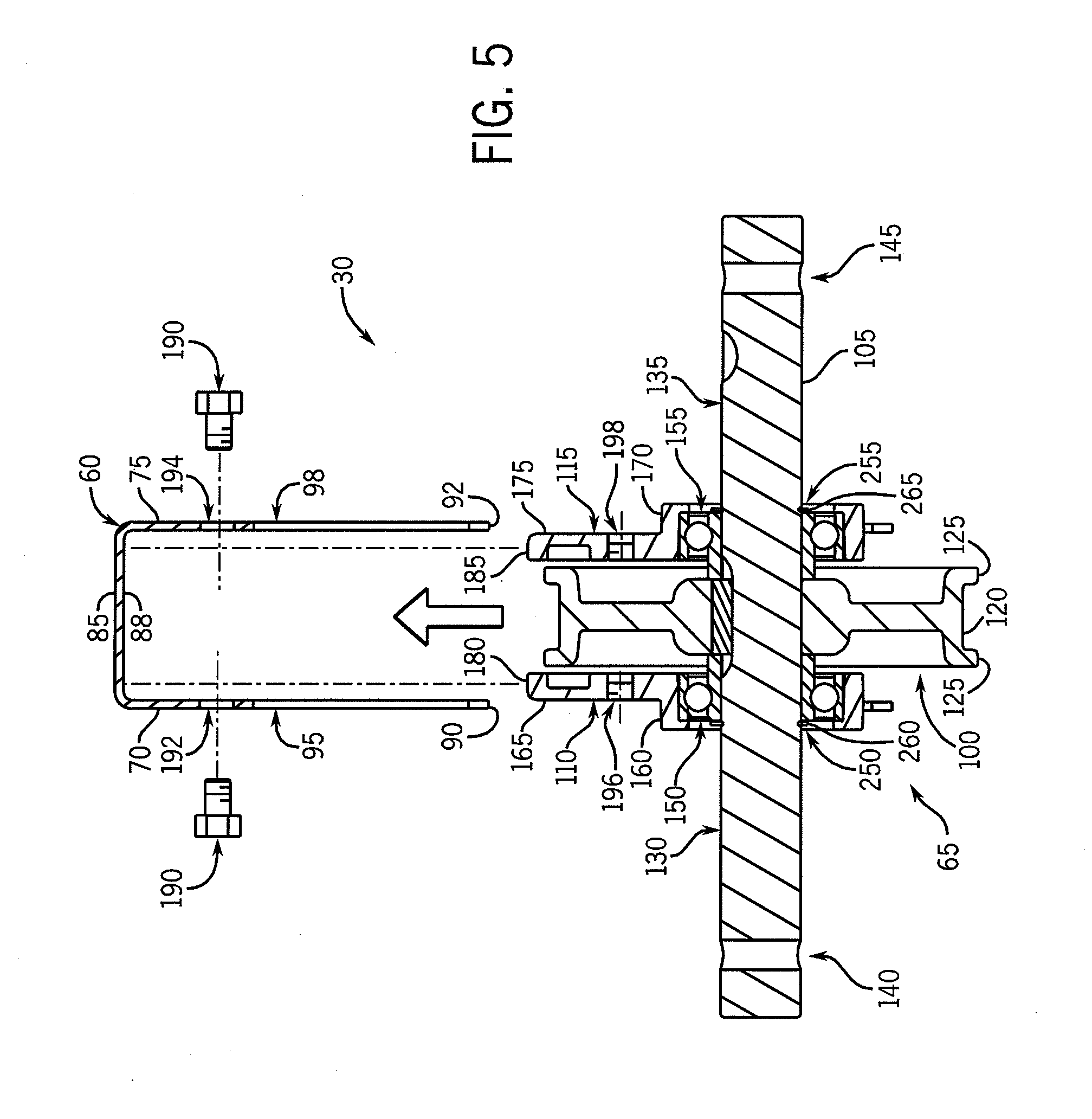
"The present invention is about a mobile storage system with a wheel mount structure that allows for easy assembly and replacement of the wheels. The wheel mount structure is designed to transfer the load to the top of the carriage, improving the life of the wheels and the carriage. The wheel assembly is modular, reducing labor and allowing for quick and easy replacement in the field. The wheel mount structure includes a structural member with sidewalls and an opening for inserting the mounting members, which are secured to the sidewalls using fasteners. The wheel assembly includes a shaft, a wheel mounted on the shaft, and mounting members that are rotatably mounted on the shaft. The wheel mount structure is easily assembled and disassembled. The technical effects of this invention include improved load carrying ability, reduced stress on the bearings, and increased operating life of the wheels and carriage."

Problems solved by technology

This construction applies significant loads to the bearings and the bolted connections, which can lead to excessive stress and premature failure of the bearings, carriage wheel assemblies, and / or the bearing connections under severe loads.

Method used


Image

  • Modular wheel assembly for a carriage in a mobile storage system
  • Modular wheel assembly for a carriage in a mobile storage system
  • Modular wheel assembly for a carriage in a mobile storage system

Examples


Embodiment Construction

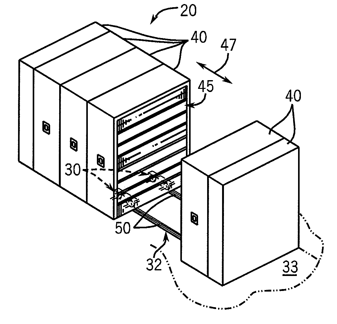
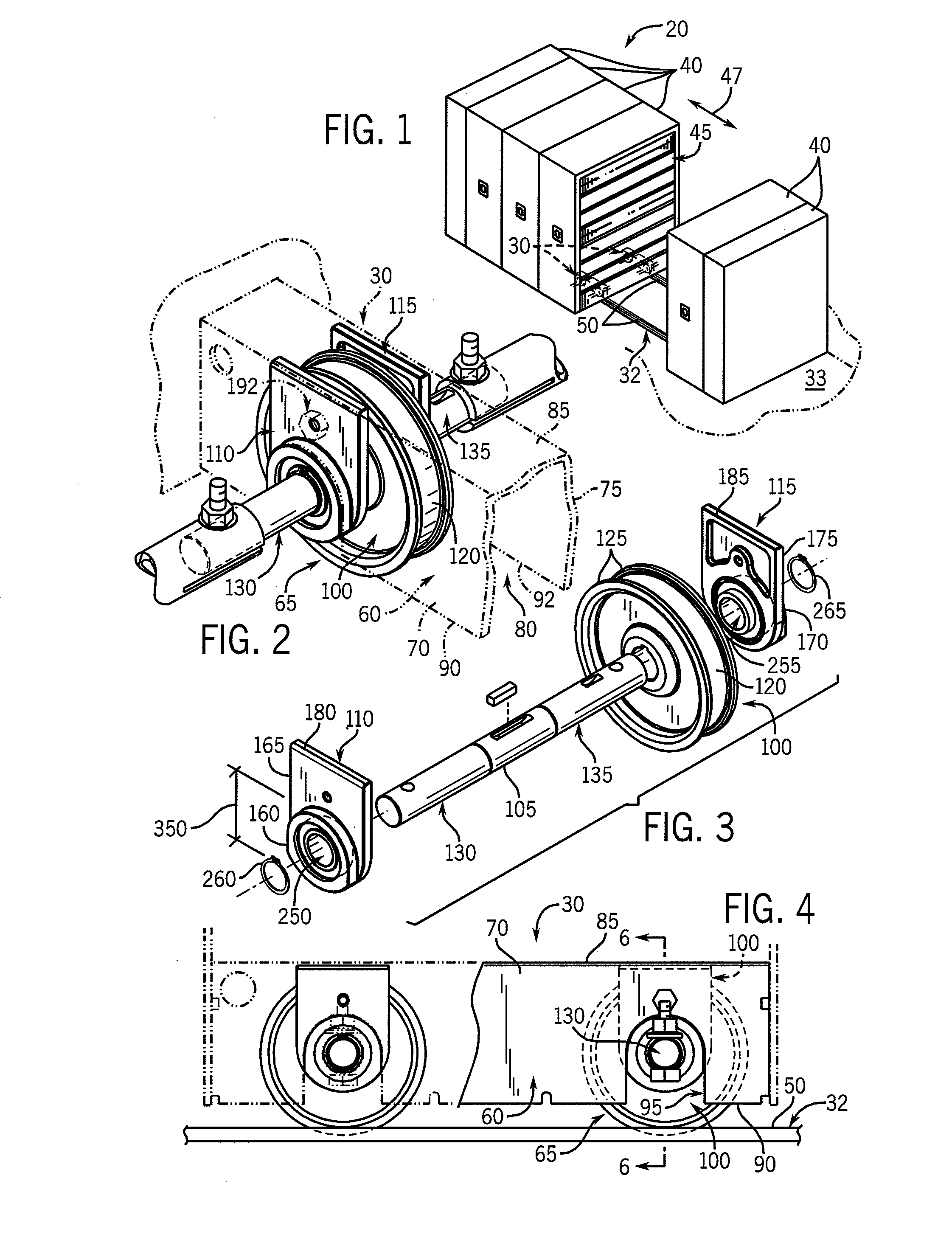
[0022]FIG. 1 illustrates a mobile storage system 20 constructed in accordance with the present invention. Mobile storage system 20 generally includes one or more carriages 30 supported on a rail system 32 that rests on a floor 33 or other supporting surface. Each carriage 30 is adapted to support one or more storage units 40. The storage units 40 are of conventional construction and generally include spaced apart sidewalls, a top wall, a bottom wall and a back wall, in a manner as is known. The illustrated storage units 40 include an open front within which a series of shelves 45 are mounted, again in a manner as is known. It should be understood that, while storage units 40 are illustrated as shelving units, carriages 30 may be use to mount any other type of storage units such as file cabinets, disc or data storage cabinets, bookcases, etc. The mobile storage system 20 may be constructed as original equipment, or may be assembled in a retrofit manner using storage units already in ...


PUM


Abstract

A carriage of a mobile storage system is adapted to support at least one storage unit for movement on a rail. The carriage generally includes a wheel mount structure, and a wheel mounting subassembly that includes a shaft having opposing ends, a wheel mounted to the shaft, and a first and a second mounting members that rotatably support the shaft. The wheel is located between the first and second mounting members such that the ends of the shaft extend outwardly from the first and second mounting members. The carriage further includes a cooperating mounting arrangement configured to non-rotatably mount the first and second mounting members to the wheel mount structure. The wheel extends downward from the wheel mount structure to engage the rail, and the ends of the shaft extend outward to engage a drive shaft that imparts rotation to the shaft and wheel so as to move the carriage on the rail.

Description

BACKGROUND AND SUMMARY OF THE INVENTION[0001]This invention relates to a mobile storage system for movably mounting storage units such as shelves or file cabinets, and more particularly to a wheel mounting arrangement for the carriage of such a mobile storage system.[0002]High density mobile storage systems are commonly used when it is desired to increase the storage capacity in a given area greater that which is attainable using fixed shelving. A typical mobile storage system employs a series of mobile platforms or carriages to which storage units such as shelves or file cabinets are mounted, and which are movably supported on a series of parallel rails. The carriages extend across the rails, and a number of storage units are mounted to and movable with each carriage. By allowing the storage units to move, the aisle space normally required between storage units for access to the storage units may be eliminated for all but one pair of storage units. This single aisle space may be sh...

Claims


Application Information

Patent Timeline
Patent Type & Authority Patents(United States)
IPC IPC(8): E01B25/22
CPCA47B53/02B65G1/10
Inventor JANSON, STEVEN L.NEMEC, BRIAN R.DINGLE, STEVEN S.
Owner SPACESAVER
Learn More