
Directed design space exploration

a technology of design space and exploration, applied in the field of programable devices, can solve the problems of extremely time-consuming and exhaustive evaluation of all possible combinations, and achieve the effects of reducing the size of the design space, reducing the time and computational effort, and improving the performance of user design

Inactive Publication Date: 2008-05-06
ALTERA CORP
View PDF3 Cites 14 Cited by
  • Summary
  • Abstract
  • Description
  • Claims
  • Application Information

AI Technical Summary

Benefits of technology

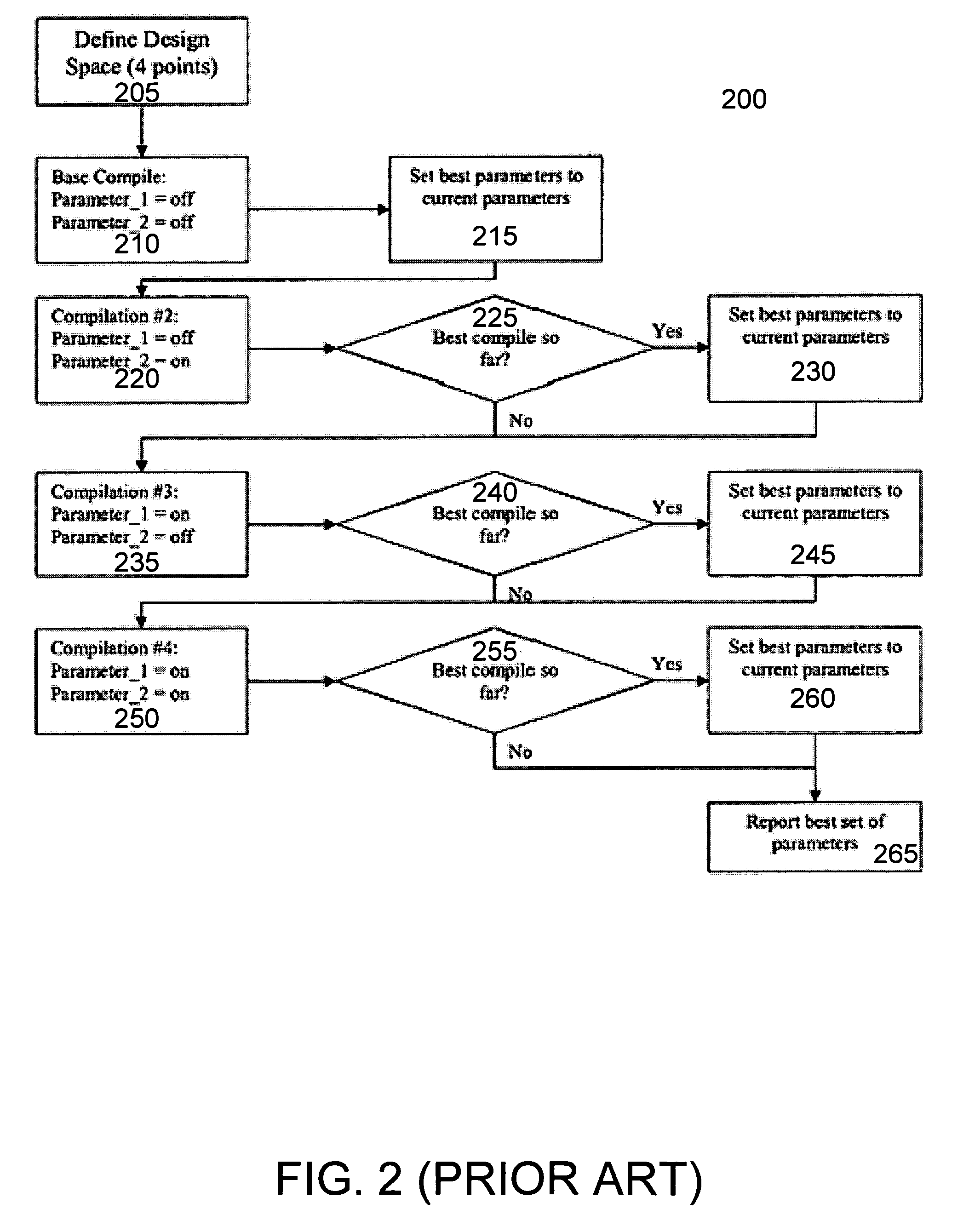
[0010]As discussed above, an exhaustive evaluation of all possible combinations is extremely time consuming. An embodiment of the invention decreases the time and computational resources needed to evaluate the input parameter settings in the design space by eliminating individual input parameter values and / or combinations of different input parameter values from the design space prior to compilation, thereby reducing the size of the design space and the time and computational effort required to evaluate the user design for the design space. An embodiment of the invention determines a probability of improvement for at least a portion of the sets of input parameter settings in the design space. The probability of improvement for a set of input parameter settings is an estimate of the likelihood that the compilation of the user design using the set of input parameter settings will improve the performance of the user design with respect to one or more design goals. Using the probability of improvement associated with a set of input parameter settings, an embodiment determines if the user design should be compiled and evaluated with these input parameter settings, or alternatively, if the compilation and evaluation of the user design with these input parameter settings should be skipped.

Problems solved by technology

As discussed above, an exhaustive evaluation of all possible combinations is extremely time consuming.

Method used


Image

  • Directed design space exploration
  • Directed design space exploration
  • Directed design space exploration

Examples


Embodiment Construction

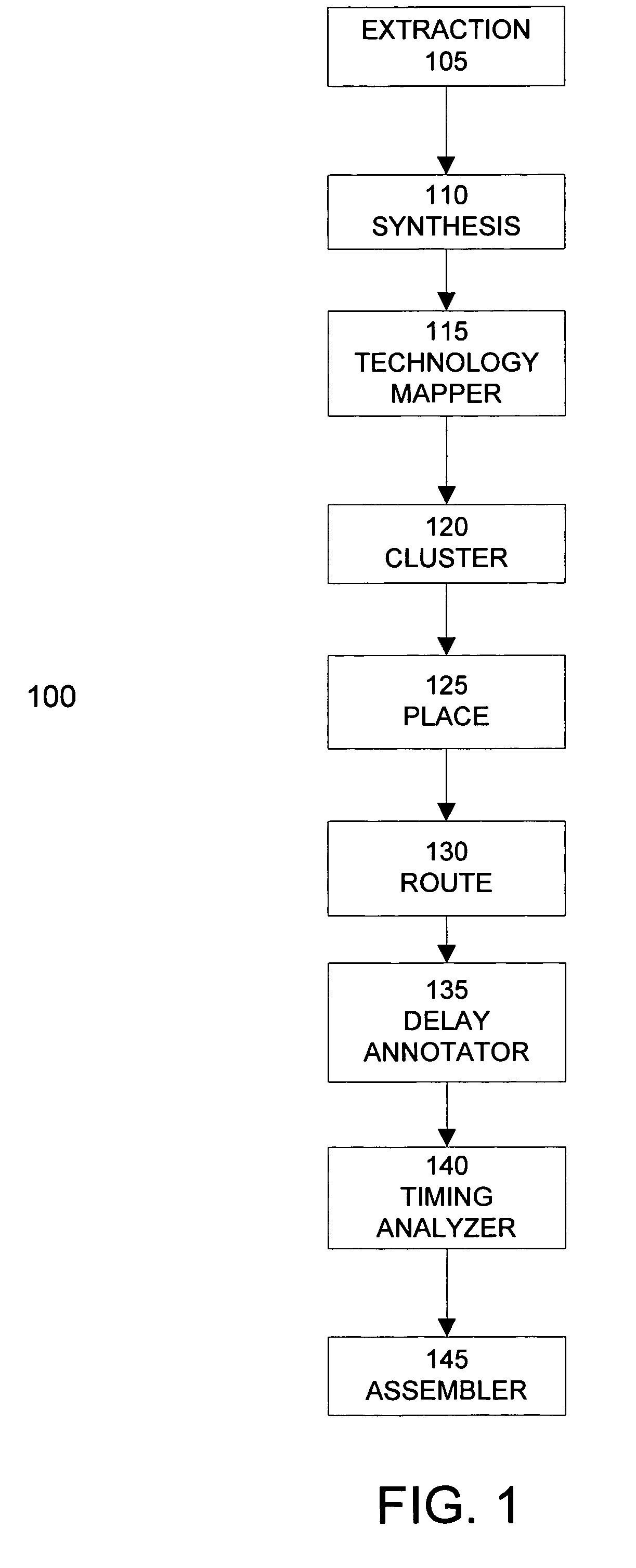
[0019]FIG. 1 illustrates the phases of a typical compilation process 100 suitable for implementing an embodiment of the invention. The compilation process 100 converts a user design into a programmable device configuration adapted to configure a programmable device to implement the user design. The extraction phase 105 converts a description of the user design, expressed for example in a hardware description language, into a register transfer layer description.

[0020]Synthesis phase 110 converts the register transfer layer description of the user design into a set of logic gates. Technology mapping phase 115 subdivides the set of logic gates into a set of atoms, which are groups of logic gates matching the capabilities of the logic cells or other functional blocks of the programmable device. A given user design may be converted into any number of different sets of atoms, depending upon the underlying hardware of the programmable device used to implement the user design.

[0021]Followin...


PUM


Abstract

The time and computational resources needed to evaluate the potential input parameter settings in a design space is decreased by determining probabilities of improvement for input parameter settings in the design space and eliminating input parameter values that have low probabilities of improvement from the design space prior to compilation. The probability of improvement for input parameter settings is an estimate of the likelihood that the compilation of the user design using the set of input parameter settings will improve the performance of the user design with respect to one or more design goals, such as timing, power, or resource usage. The probability of improvement for input parameter settings can be determined from an analysis of the compilation results of sample designs, from attributes and / or constraints of the user design, and / or from a correlation between the results of optimization algorithms applied to the user design.

Description

CROSS-REFERENCES TO RELATED APPLICATIONS[0001]This patent application is related to U.S. patent application Ser. No. 10 / 625,505, filed Jul. 23, 2003, and entitled “Techniques for Automated Sweeping of Parameters in Computer Aided Design to Achieve Optimal Performance and Resource Usage,” and incorporates by reference the disclosure of this application herein for all purposes.BACKGROUND OF THE INVENTION[0002]The present invention relates to the field of programmable devices, and the systems and methods for programming the same. Programmable devices, such as FPGAs, typically includes thousands of programmable logic cells that use combinations of logic gates and / or look-up tables to perform a logic operation. Programmable devices also include a number of functional blocks having specialized logic devices adapted to specific logic operations, such as adders, multiply and accumulate circuits, phase-locked loops, and memory. The logic cells and functional blocks are interconnected with a ...

Claims


Application Information

Patent Timeline
IPC IPC(8): G06F17/50
CPCG06F17/5054G06F2217/08G06F2111/06G06F30/34
Inventor CHESAL, IANBORER, TERRY
Owner ALTERA CORP
Learn More