
Method and system for timing controlled signal transmission in a point to multipoint power line communications system

Active Publication Date: 2008-05-06
ARKADOS
View PDF17 Cites 97 Cited by
  • Summary
  • Abstract
  • Description
  • Claims
  • Application Information

AI Technical Summary

Benefits of technology

[0011]FDM further provides that an allocated time period of a timing frame can be partitioned to a greater extent, and therefore among greater numbers of remotes, such that a head-end has the ability to simultaneously transmit to multiple remotes utilizing different sets of tones for each remote. Alternatively, multiple remotes can transmit to the head-end within the same allocated time period, where each remote uses a specific set of tones.
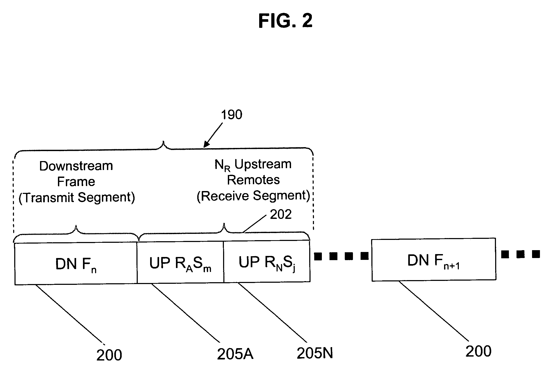
[0012]In a preferred embodiment where the head-end is the source of distribution point for the bulk of the data communicated in the point to multipoint PLC network, the head-end controls the timing of PLC signal transmissions from itself to all of the remotes and from each of the remotes to itself.

Problems solved by technology

As such, system complexity is required to support transmission detection and synchronization for each PLC device in the network.
First, adhoc administration of communications involves an overhead associated with media access and node synchronization and also can result in increased latency, which can degrade the quality of communications services being provided.
Furthermore, networks that operate based on adhoc types of media access typically show a considerable degradation in bandwidth utilization as the number of communication nodes increases.
In addition, as each of the remotes is typically utilized by a different customer located within a same point to multipoint network, the decoding of all PLC signals present on the PLC network by each of the remotes creates difficulties in maintaining isolation and security between the remotes.
Consequently, in many prior art point to multipoint PLC systems, data distributed to one customer from the head-end is not isolated and protected to prevent other customers on the same network from accessing the data.

Method used


Image

  • Method and system for timing controlled signal transmission in a point to multipoint power line communications system
  • Method and system for timing controlled signal transmission in a point to multipoint power line communications system
  • Method and system for timing controlled signal transmission in a point to multipoint power line communications system

Examples


Embodiment Construction

[0022]The present invention of timing controlled transmission of PLC signals in a point to multipoint PLC system is explained in connection with operations performed at a head-end PLC transceiver and remote PLC transceivers of an OFDM PLC system in which PLC data signals are conveyed over conventional utility electrical power media. It is to be understood, however, that the present invention can be implemented using other frequency division multiplexing PLC system configurations or where all of the PLC signal transmissions have frequencies within a single operating frequency bandwidth.

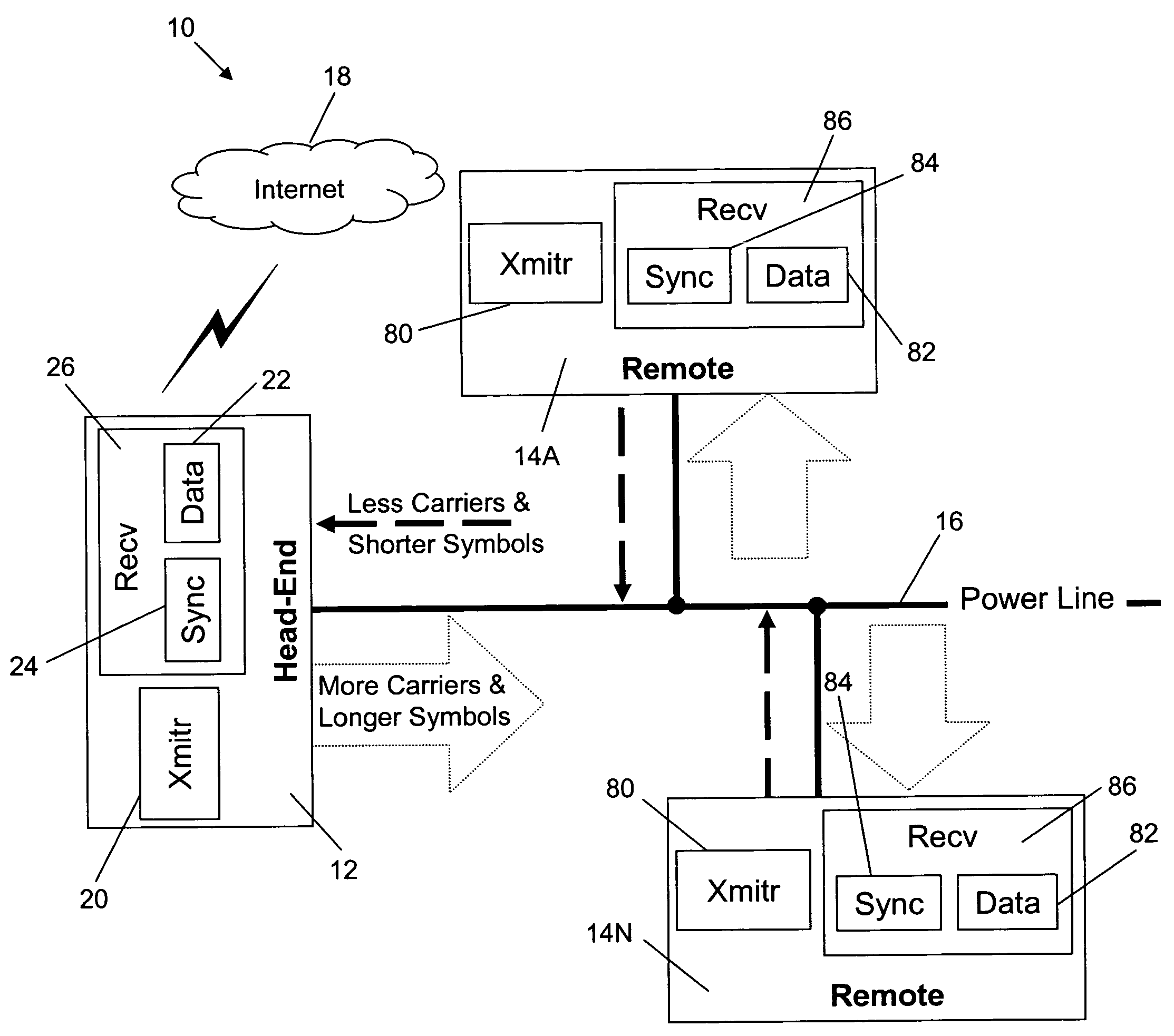
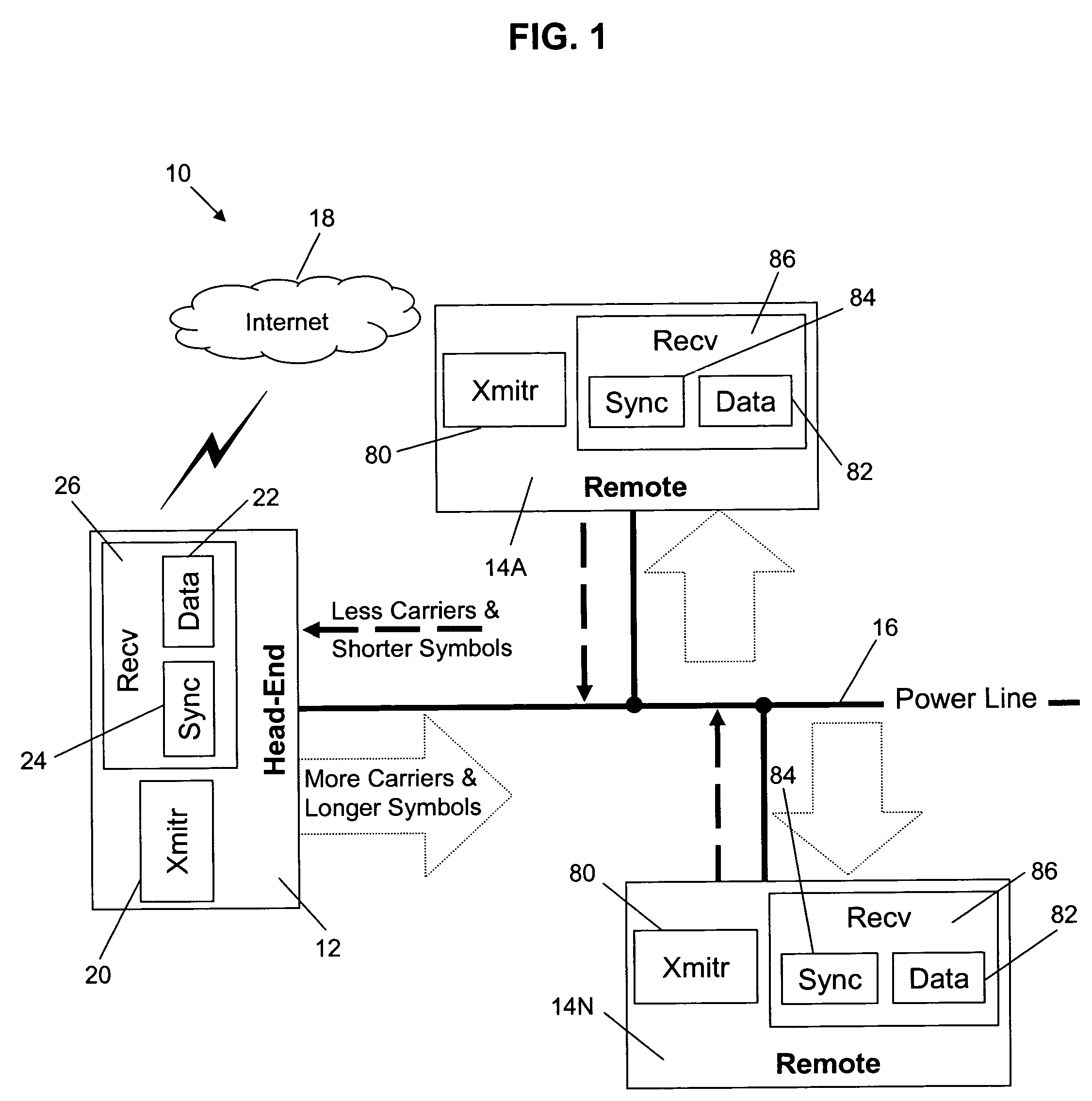
[0023]FIG. 1 illustrates an exemplary point to multipoint PLC system 10 which provides for timing controlled PLC signal transmissions in accordance with the present invention. Referring to FIG. 1, a head-end PLC transceiver 12 couples sites on the Internet 18 to a power line network 16. The system 10 further includes a plurality of remote PLC transceivers 14 (only remotes 14A and 14N are shown) which a...


PUM


Abstract

Power line communication (“PLC”) signals are transmitted between a head-end PLC transceiver coupled to multiple remote PLC transceivers over a electric power and communications distribution network in accordance with a timing controlled PLC data frame which determines how much bandwidth is allocated to downstream transmission from the head-end to the remotes and to upstream transmissions from one or more of the remotes to the head-end. The configuration of the timing controlled data frame can be dynamically modified to achieve higher bandwidth for the downstream traffic and to satisfy changing bandwidth needs of each remote.

Description

CROSS REFERENCE TO RELATED APPLICATIONS[0001]This application claims the benefit of U.S. Provisional Application No. 60 / 413,302 filed Sep. 25, 2002 and U.S. Provisional Application No. 60 / 415,111 filed Sep. 30, 2002, which are incorporated by reference herein.FIELD OF THE INVENTION[0002]This invention relates to the field of communications over conventional electric power conveying media, and more particularly, to allocating bandwidth for power line communications (“PLC”) signal transmissions among PLC transceiver nodes and more specifically between a head-end PLC transceiver and remote PLC transceivers in a point to multipoint PLC system.BACKGROUND OF THE INVENTION[0003]The delivery of broadband data communications services, such as Internet traffic, telephony, broadcast TV and video-on-demand, to homes and business over existing power distribution systems is very attractive to content service providers as well as their customers. The power distribution systems can constitute, for ...

Claims


Application Information

Patent Timeline
IPC IPC(8): H04J3/06H04B3/54H04L5/02H04L5/14
CPCH04B3/542H04L5/023H04L5/1484H04B2203/5416H04B2203/5441H04B2203/545H04B2203/5483H04B2203/5491
Inventor LOGVINOV, OLEGWALVIS, DIRKDURFEE, LAWRENCE F.
Owner ARKADOS
Learn More