
Implementation of output floating scheme for hv charge pumps

a floating scheme and charge pump technology, applied in the direction of electric variable regulation, process and machine control, instruments, etc., can solve the problems of high current demand, low efficiency, and large increase in the overall power requirements of the memory devi

Active Publication Date: 2008-05-06
SANDISK TECH LLC
View PDF35 Cites 73 Cited by
  • Summary
  • Abstract
  • Description
  • Claims
  • Application Information

AI Technical Summary

Benefits of technology

[0006]According to different embodiments of the present invention, various methods, devices and systems are described for managing power in a non-volatile memory system having a high voltage charge pump and associated regulator. A method of managing power in a non-volatile memory system having a high voltage charge pump and associated regulator is described. The method includes the following operations, receiving an operation command corresponding to an operation, pumping up a charge pump output voltage to a desired output voltage co...

Problems solved by technology

However, with currently available high voltage charge pump designs, efficiencies are typically low, in the range of approximately 5% to 10% which means that the charge pump itself must use, for example, 10 mA of current in order to deliver 100 uA of current to an output node.
This high current demand adds substantially to the overall power requirements of the memory device.
In any case, these additional current requirements unnecessarily add to the overall power consumption of the device and are therefore wasteful and costly.

Method used


Image

  • Implementation of output floating scheme for hv charge pumps
  • Implementation of output floating scheme for hv charge pumps
  • Implementation of output floating scheme for hv charge pumps

Examples


Embodiment Construction

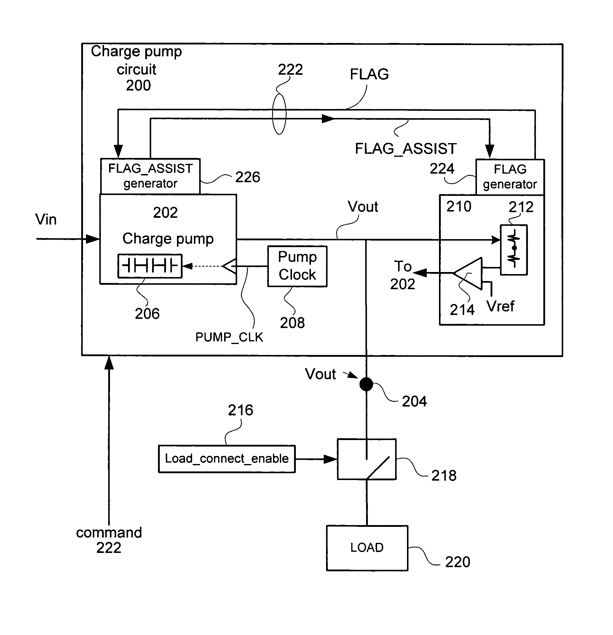
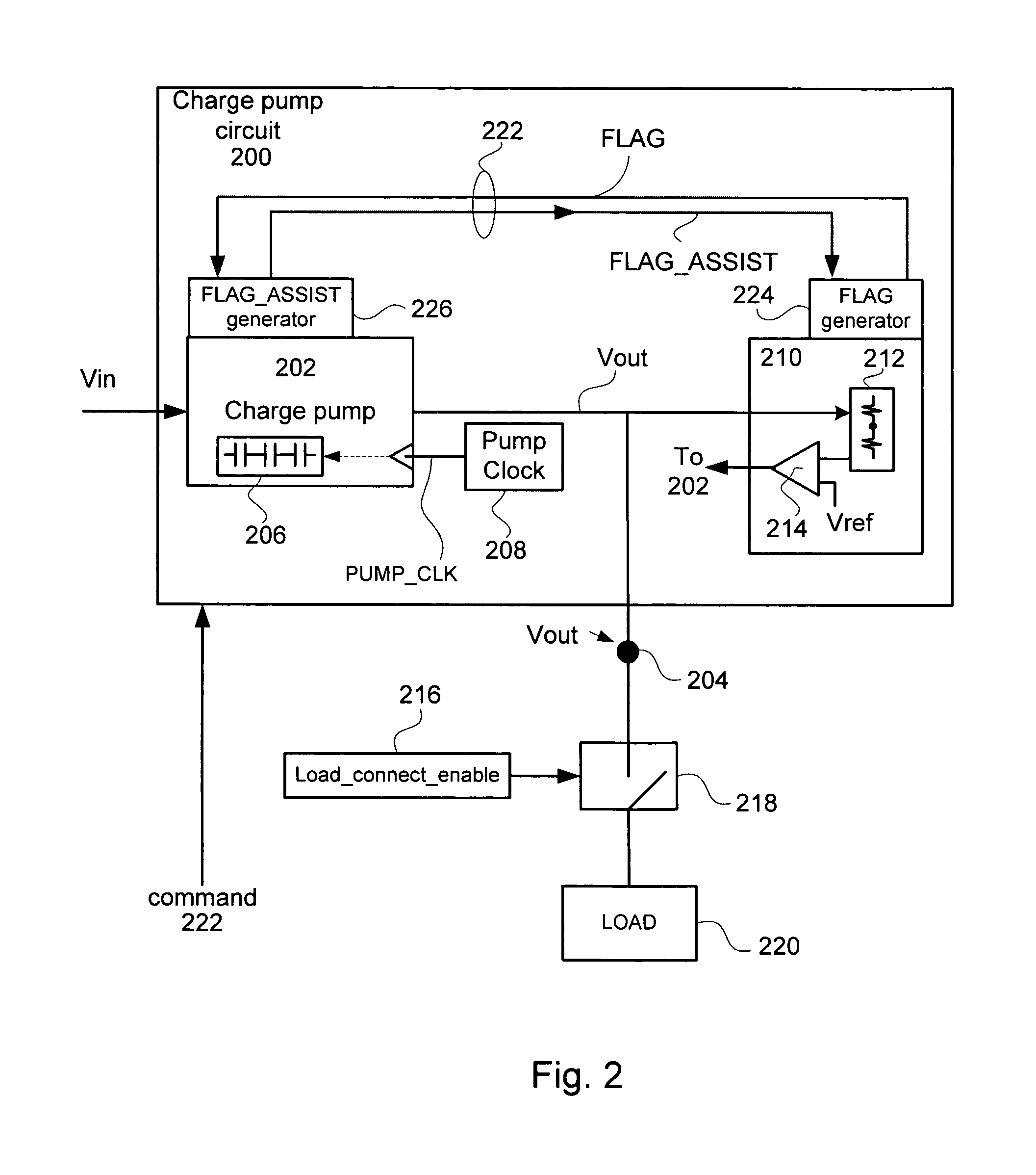
[0013]Reference will now be made in detail to a particular embodiment of the invention an example of which is illustrated in the accompanying drawings. While the invention will be described in conjunction with the particular embodiment, it will be understood that it is not intended to limit the invention to the described embodiment. To the contrary, it is intended to cover alternatives, modifications, and equivalents as may be included within the spirit and scope of the invention as defined by the appended claims.

[0014]The invention provides for managing the overall power consumption of charge pumps in a non-volatile memory device. In the described embodiment, after a load is connected to a charge pump in regulation, both the charge pump and the regulator are turned off. In particular, when the charge pump has achieved a desired output voltage level (Vpgm, for example) and is in regulation (i.e., the associated regulator is providing the requisite DC current to maintain the desired ...


PUM


Abstract

According to different embodiments of the present invention, various methods, devices and systems are described for managing power in charge pumps in a non-volatile memory system having a high voltage charge pump and associated regulator. A method includes the following operations, receiving an operation command corresponding to an operation, pumping up a charge pump output voltage to a desired output voltage, turning off the regulator and the charge pump when the output voltage is approximately the desired output voltage compensating for charge sharing by turning on the charge pump and setting a pump clock rate to a slow clock rate in order to avoid overshooting the desired output voltage by the charge pump while the operation is being carried out, and compensating for junction leakage by turning on the regulator and the charge pump until the charge pump output voltage is the desired output voltage.

Description

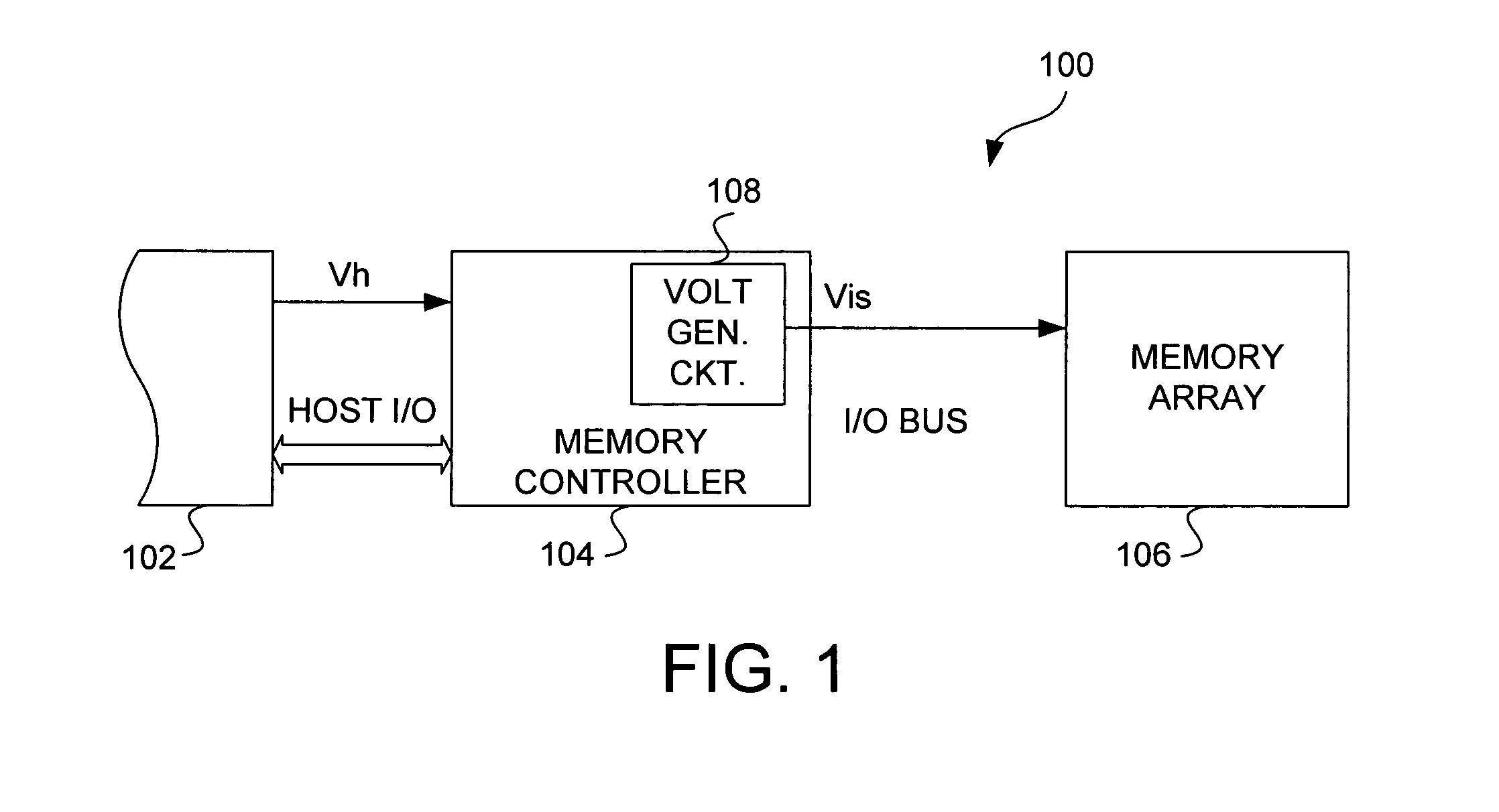
FIELD OF THE INVENTION[0001]The present invention relates generally to non-volatile memory devices. More particularly, the present invention relates to a method for managing power consumption by high voltage charge pumps used in FLASH memory devices.BACKGROUND[0002]Memory cards are commonly used to store digital data for use with various products (e.g., electronics products). Examples of memory cards are flash cards that use Flash type or EEPROM type memory cells (also referred to as FLASH memory cells) to store the data. Flash cards have a relatively small form factor and have been used to store digital data for products such as cameras, hand-held computers, set-top boxes, hand-held or other small audio players / recorders (e.g., MP3 devices), and medical monitors. A major supplier of flash cards is SanDisk Corporation of Sunnyvale, Calif. Unlike standard MOS transistors, FLASH memory cells contain a floating gate that is electrically isolated and located between a control gate and a...

Claims


Application Information

Patent Timeline
IPC IPC(8): G05F1/10
CPCG11C5/145G11C16/30
Inventor GOVINDU, PRASHANTIPAN, FENGMUI, MANKWON, GYUWANPHAM, TRUNGWANG, CHI-MING
Owner SANDISK TECH LLC
Learn More