Universal putter
a technology of putter and shaft, applied in the field of golf putter, to achieve the effect of effectively locking the shaft in a single position
- Summary
- Abstract
- Description
- Claims
- Application Information
AI Technical Summary
Benefits of technology
Problems solved by technology
Method used
Image
Examples
first embodiment
Description of a First Embodiment
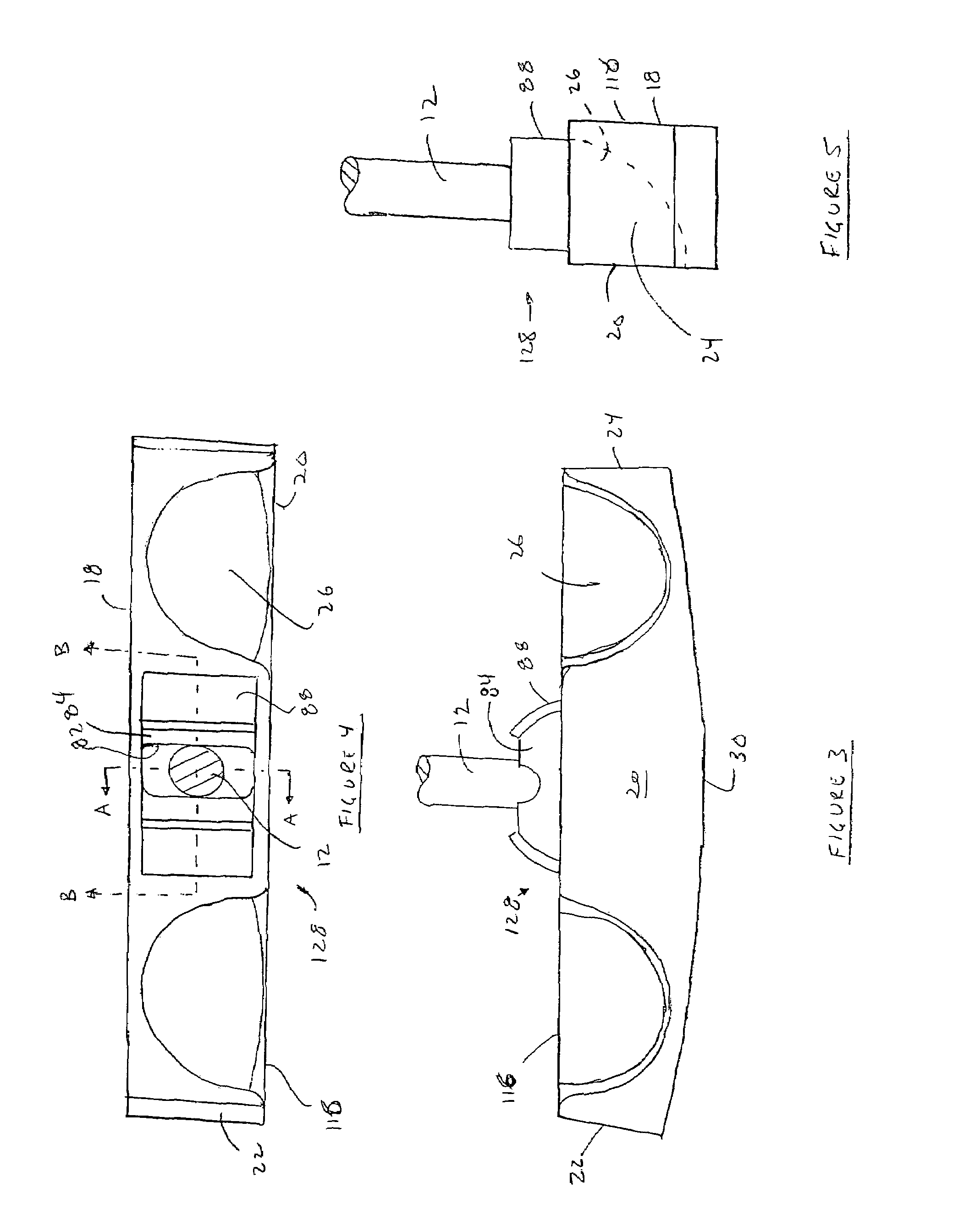
[0038]FIGS. 3, 4 and 5 show a first head 116 connected to a shaft 12 through a first connection 128. The first head 116 has a face 18, first end 22, second end 24 and ball scoops 26 as described above. The first head 116 is about 5.5 to 5.75 inches long, about 1 to 1.25 inches wide and about 1 inch high although other suitable dimensions may also be used. The length of the first head 116 helps distribute the weight away from the center of the first head 116, which increases the size of the “sweet spot” while also providing room for two ball scoops 26. The ball scoops 26 are roughly in the shape of a quarter of a sphere of a radius slightly larger than a golf ball, for example between about 0.86 and 0.88 inches. The ball scoops 26 may be given a radius where they intersect with the side 20 of the second head 116 to allow a golf ball to roll into them more easily. The shape of the ball scoops 26 may also deviate from a perfect sphere to better hold a g...
second embodiment
Description of a Second Embodiment
[0042]FIGS. 9, 10 and 11 show a second head 216 connected to a shaft 12 through a second connection 228. The second head 216 is shaped generally as described in the first paragraph of the description of the first embodiment except as required for the second connection 228.
[0043]The second connection 228 is shown in FIGS. 9 to 14. A sphere or ball 232 is attached to the end of the shaft 12. The ball 232 may be made of metal and attached to the shaft 12, for example, by gluing, pinning or threading the ball 232 to the shaft 12. The ball 232 fits inside of a cavity 234 in the second head 216. There is at least a slight clearance all around the ball 232 so that, while the cavity 234 may prevent the ball 232 from moving laterally out of position, the ball 232 is free to rotate within the cavity 234. The ball 232 is also positioned by, and seated in, a pair of rubber O-rings 36. A lower O-ring 36a rests on the bottom of the cavity 234 and holds the bottom...
third embodiment
A Third Embodiment
[0047]FIG. 16 shows a third head 316 connected to a shaft 12 through a third connection 328. The third head 316 is shaped generally as described in the description of the first embodiment except for the differences described below.
[0048]Referring to FIGS. 16 and 17, a third ball 332 is attached to the end of the shaft 12. The third ball 332 fits inside of a third cavity 334 in the third head 316. The third cavity 334 may prevent the third ball 332 from moving laterally out of position, but does not prevent the third ball 332 from rotating. The third ball 332 is also positioned by and seated in an upper O-ring 36b, which may be made of rubber, nylon or other materials depending on the degree of friction desired. In place of, or in addition to, the lower O-ring 36a of the second embodiment, a screw 66 protrudes into the third cavity 334 and contacts the bottom of the third ball 332. The screw 66 is threaded into the bottom of the third head 316 and may engage a tool,...
PUM
 Abstract
Description
Claims
Application Information
 - R&D
- Intellectual Property
- Life Sciences
- Materials
- Tech Scout
- Unparalleled Data Quality
- Higher Quality Content
- 60% Fewer Hallucinations
Browse by: Latest US Patents, China's latest patents, Technical Efficacy Thesaurus, Application Domain, Technology Topic, Popular Technical Reports.
© 2025 PatSnap. All rights reserved.Legal|Privacy policy|Modern Slavery Act Transparency Statement|Sitemap|About US| Contact US: help@patsnap.com


