
Handover control apparatus, relay router, gateway apparatus, access router base station, mobile communication system, and handover control method

Inactive Publication Date: 2008-04-22
NTT DOCOMO INC
View PDF14 Cites 4 Cited by
  • Summary
  • Abstract
  • Description
  • Claims
  • Application Information

AI Technical Summary

Benefits of technology

[0007]The present invention has been accomplished in view of the above problem and an object of the present invention is to realize a packet forward through an optimal path to a radio terminal unit after a handover, regardless of the topologies, thereby effectively utilizing the network resources and preventing the occurrence of the miss-ordering of packets and, as a consequence, to provide a handover control apparatus, a relay router, a gateway apparatus, an access router, a base station, a mobile communication system, and a handover control method for efficiently performing handover control.
[0078]According to these aspects of the invention, determined as the COR is a relay router with which the sum of the numbers of relay routers for every candidate access router for the destination of the radio terminal unit is minimum, out of the candidate relay routers for the COR. Efficient handover control can be implemented by using a path with the smaller number of relay routers for the packet forward. According to these aspects of the invention, a communication device with the minimum sum of the numbers of relay routers for every candidate access router for the destination of the radio terminal unit is selected as the COR, and thus the efficient handover control can be performed. Namely, if packets to the radio terminal unit are buffered in this COR during the handover, the packets can be forwarded through the optimal path to the radio terminal unit after the handover; it is thus feasible to effectively utilize the network resources and to prevent the occurrence of the miss-ordering of packets.

Problems solved by technology

The major topologies (connection forms) in the mobile communication systems are generally classified under the tree type and the mesh type, and in either case of these topologies, there arose the problem as described below about the handover control.
For this reason, a redundant path is made between the old AR and the new AR, so as to result in waste of network resources.
This causes the packets routed via the respective communication paths to arrive in a mixed state, and thus raises concern about occurrence of a miss-ordering of packets during the handover.

Method used


Image

  • Handover control apparatus, relay router, gateway apparatus, access router base station, mobile communication system, and handover control method
  • Handover control apparatus, relay router, gateway apparatus, access router base station, mobile communication system, and handover control method
  • Handover control apparatus, relay router, gateway apparatus, access router base station, mobile communication system, and handover control method

Examples


first embodiment

[0093]The first embodiment of the present invention will be described below in detail with reference to the drawings.

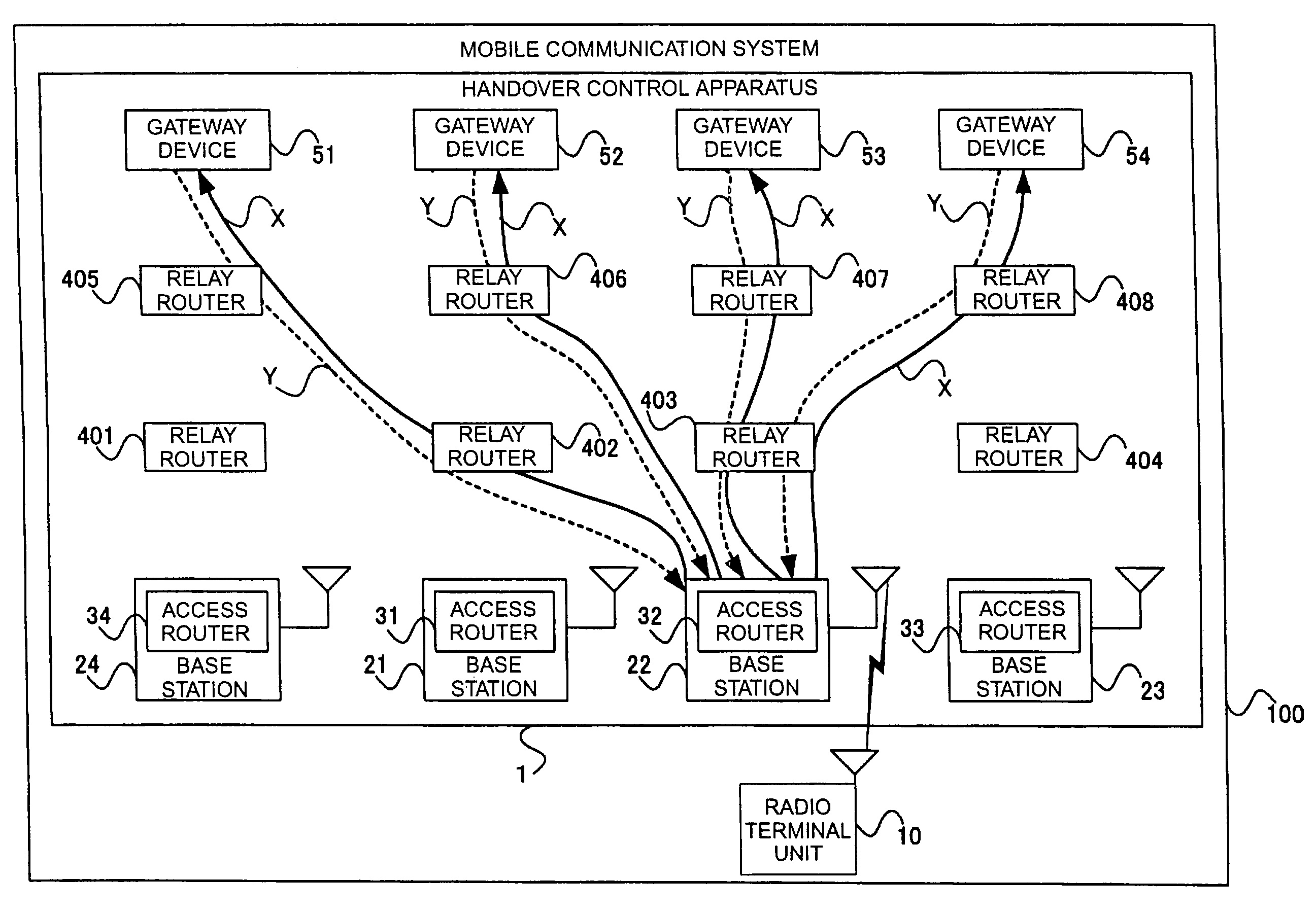
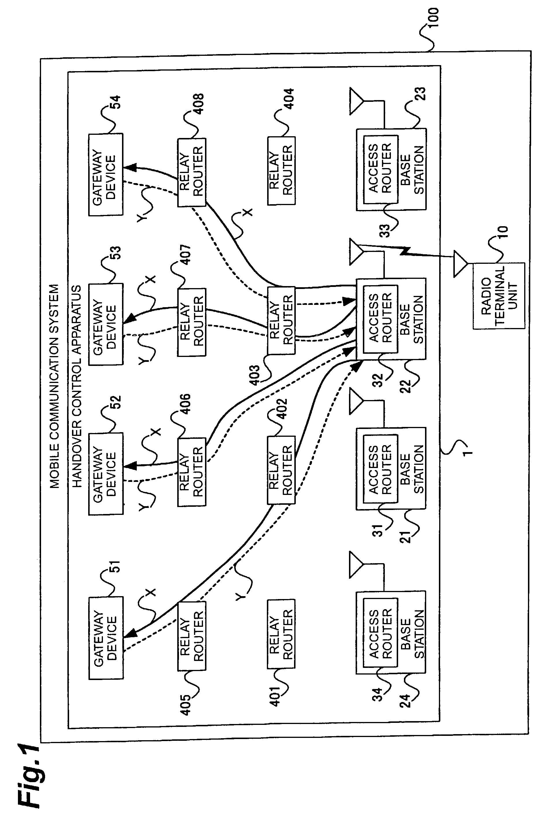
[0094]FIG. 1 is a block diagram showing a configuration of the mobile communication system in the first embodiment of the present invention. The mobile communication system 100 shown in FIG. 1 comprises handover control apparatus 1 and radio terminal unit 10 such as a cellular phone or the like. The handover control apparatus 1 is comprised of a plurality of base stations 21, 22, 23, 24 for radio communication with the radio terminal unit 10; access routers 31, 32, 33, 34 provided in these base stations 21 to 24; relay routers 401 to 408 directly or indirectly connected to these access routers 31 to 34; and gateway devices 51, 52, 53, 54.

[0095]The gateway devices 51-54, the relay routers 401-408, and the access routers 31-34 will be hereinafter called collectively “communication devices,” for convenience′ sake of description. The communication devices constitute the m...

second embodiment

[0123]The second embodiment of the present invention will be described below in detail with reference to the drawings. In the first embodiment, the COR was determined on the basis of the number of relay routers from the gateway device to the candidate access router for the destination of the radio terminal unit. In contrast to it, the present embodiment is configured so that the COR is determined on the basis of the number of relay routers from a candidate relay router or gateway device for the COR to every candidate access router for the destination of the radio terminal unit.

[0124]The major configuration of the mobile communication system in the present embodiment is much the same as the configuration of the mobile communication system 100 described with reference to FIG. 1, and thus the illustration and detailed description of the configuration are omitted herein while the components are denoted by the same reference symbols. The following will detail the COR determining method i...

third embodiment

[0150]The third embodiment of the present invention will be described below in detail with reference to the drawings. In the second embodiment, the relay router or the gateway device was used to determine the COR candidate and COR. In contrast to it, the access router is used to determine the COR candidate and COR in the present embodiment.

[0151]The principal configuration of the mobile communication system in the present embodiment is much the same as the configuration of the mobile communication system 100 described with reference to FIG. 1, and thus the illustration and detailed description of the configuration are omitted herein while the same reference symbols denote the components. The following will detail the COR determining method in the mobile communication system in the third embodiment.

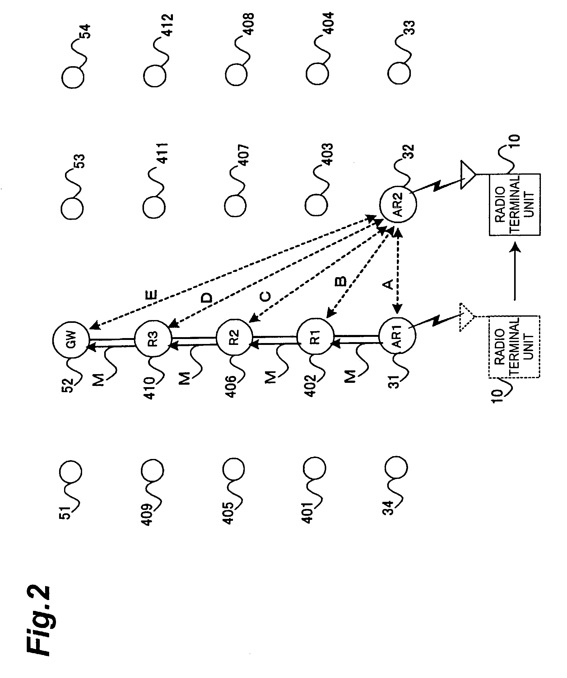
[0152]FIG. 9 is a schematic diagram showing a positional relation among the access routers, relay routers, and gateway devices constituting the handover control apparatus in the present em...


PUM


Abstract

A mobile communication system 100 according to the present invention comprises handover control apparatus 1 and radio terminal unit 10. The handover control apparatus 1 controls handover of a radio terminal unit 10 between access routers 31-34 provided in respective base stations 21-24 for radio communication with the radio terminal unit 10. The handover control apparatus 1 counts the number of relay routers for every candidate access router 32-34 for a destination of the radio terminal unit 10, from a gateway device 52 and determines a COR on the basis of the number of relay routers for every access router 32, 33, 34 thus counted.

Description

BACKGROUND OF THE INVENTION[0001]1. Field of the Invention[0002]The present invention relates to a handover control apparatus, a relay router, a gateway apparatus, an access router, a base station, a mobile communication system, and a handover control method.[0003]2. Related Background Art[0004]In recent years, packet communication with high utilization efficiency of communication links is used for transmission and reception of data between radio terminal units including cellular phones. In the packet communication, a handover involves a process of switching an access router (AR; Access Router) for transmitting packets to the radio terminal unit, over to another. And there is concern that some packets fail to arrive at the radio terminal unit during the handover (packet loss). In order to reduce the packet loss, packets transmitted from a correspondent node with the radio terminal unit were thus buffered during the handover in the old access router before the handover, and the packe...

Claims


Application Information

Patent Timeline
IPC IPC(8): H04Q7/00H04L45/122H04L45/851H04W36/08H04W36/10H04W36/38H04W40/34
CPCH04L45/122H04W36/02H04W40/36
Inventor ISOBE, SHINICHIIGARASHI, KENIWASAKI, ATSUSHINISHIMURA, KENJIKOSHIMIZU, TAKASHI
Owner NTT DOCOMO INC
Learn More