Spot joining method of metal members and spot joining apparatus of metal members

a metal member and spot joining technology, applied in the direction of soldering apparatus, manufacturing tools,auxillary welding devices, etc., can solve the problems of limited methods, increased manufacturing costs, and difficulty in joining light metals such as aluminum, and achieve the effect of stable joining position and sufficient joining strength

Active Publication Date: 2008-04-22
MAZDA MOTOR CORP
View PDF20 Cites 9 Cited by
  • Summary
  • Abstract
  • Description
  • Claims
  • Application Information

AI Technical Summary

Benefits of technology

[0010]The present invention has been devised in view of the above-described problems. An object to of the present invention to provide a spot joining method of metal members and a spot joining apparatus of metal members, in which different kinds of metal members are joined by a frictional agitation, which can provide such a stable joining position, even if the pin of the rotating tool is short, that the aluminum materials can be prevented from being accumulated on the rotating tool, the appearance of joining surfaces can be prevented from deteriorating, and the sufficient joining strength can be obtained.

Problems solved by technology

Light metals such as aluminum, however, have somewhat difficulties in joining by an electric resistance welding.
Accordingly, there were problems that their joining methods might be limited and manufacturing costs might increase.
Herein, although the above-described frictional agitation joining apparatus may be available for joining different kinds of metal members, it is not easy to agitate, especially, the aluminum member and the steel member properly, which have different melting points from each other.
Here, since an oxidation film is generally created on a surface of the steel member, a sufficient joining strength may not be obtained properly without any useful measures.
However, there may be another difficulty in adopting this proposed method.
In this case, however, such a short pin may provide somewhat difficulty in positioning the rotating pin at a specified portion stably, resulting in an unstable joining position.
This unstable joining position may cause an improper joining.
As a result, there may occur other problems that aluminum materials are accumulated on the rotating tool, an appearance of joining surfaces deteriorates, the sufficient joining strength is not obtained, and the like.

Method used


Image

  • Spot joining method of metal members and spot joining apparatus of metal members
  • Spot joining method of metal members and spot joining apparatus of metal members
  • Spot joining method of metal members and spot joining apparatus of metal members

Examples


Embodiment Construction

[0042]Hereinafter, preferred embodiments of the present invention will be described with reference to the accompanying drawings.

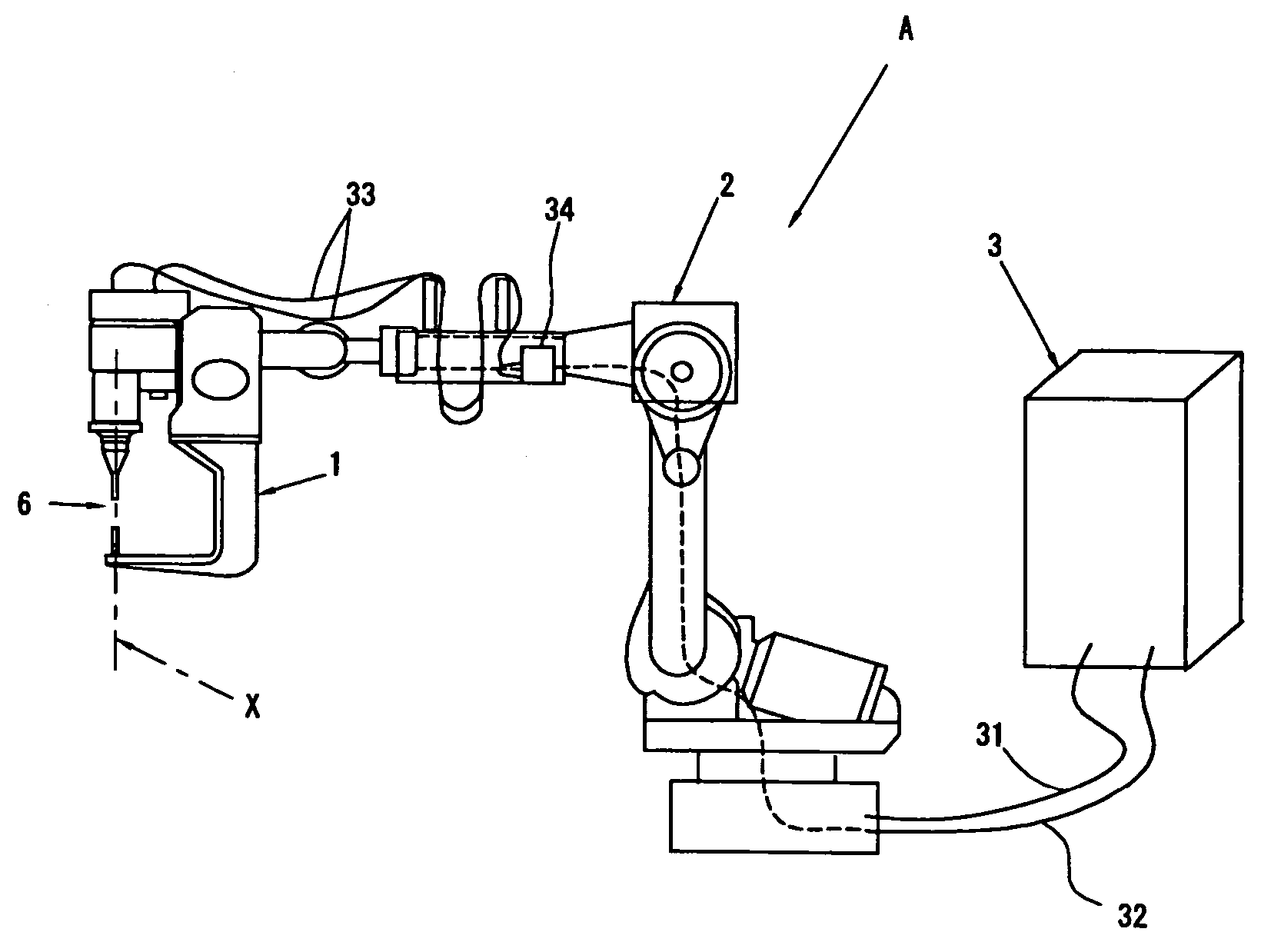
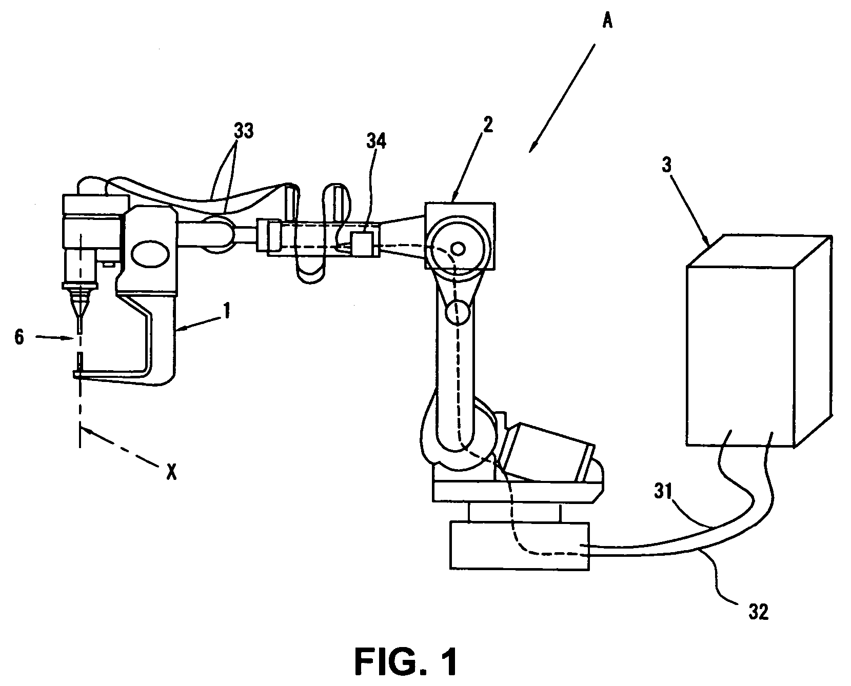
[0043]FIG. 1 illustrates schematically a structure of a joining apparatus A according to an embodiment, in which an aluminum plate W1 made of an aluminum alloy (a Japanese Industrial Standard 6000 based aluminum-alloy plate) and a steel plate W2 (a zinc plating steel plate) are used as metal members which constitutes, for example, a vehicle body or the like, and the both plates are partly lapped and joined to each other.

[0044]The joining apparatus A includes a robot 2, a joining gun 1 attached to an arm tip of the robot, and a control unit 3 to control these.

[0045]The robot 2 may be configured of, for example, a six-axis multiple-articulated type of robot which has been used widely, which has function of positioning the joining gun 1 at a joining portion between the aluminum plate W1 and the steel plate W2.

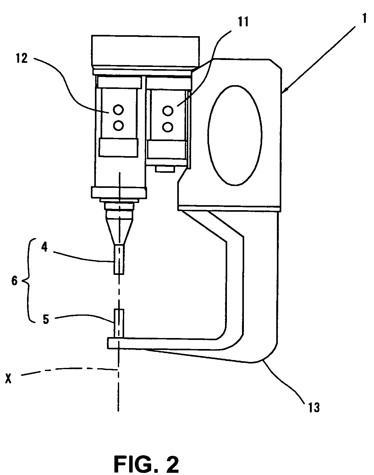
[0046]The joining gun 1 includes a rotating toll 4 ...


PUM

PropertyMeasurementUnit
angleaaaaaaaaaa
lengthaaaaaaaaaa
lengthaaaaaaaaaa

Abstract

In a spot joining method and apparatus, pressing force of a rotating tool is maintained at a first pressing force, the frictional heat due to the rotation of the rotating tool is generated on a surface of an aluminum plate, and the aluminum plate is softened by this frictional heat, so as to ensure the centering of a pin portion of the rotating tool. Thus, even if the pin of the rotating tool is short, a stable joining position can be obtained, so that the aluminum material can be prevented from accumulating on the rotating tool, the appearance of joining surfaces can be prevented from deteriorating, and the sufficient joining strength can be obtained.

Description

BACKGROUND OF THE INVENTION[0001]The present invention relates to a spot joining method of metal members and a spot joining apparatus of metal members, and more specifically to a spot joining method and a spot joining apparatus in which different kinds of metal members are joined by a frictional joining method.[0002]Recently, some vehicle bodies made of light metals, such as aluminum, have been manufactured aiming at lightweight vehicles. Light metals such as aluminum, however, have somewhat difficulties in joining by an electric resistance welding. Accordingly, there were problems that their joining methods might be limited and manufacturing costs might increase.[0003]Meanwhile, a frictional agitation joining apparatus disclosed in Japanese Patent Laid-Open Publication No. 2003-117668 has been proposed. In this frictional agitation joining apparatus, a rotator having a pin at its tip is rotated at a high speed and then pressed against a work (an aluminum plate). The work is softene...

Claims


Application Information

Patent Timeline
Patent Type & Authority Patents(United States)
IPC IPC(8): B23K20/12B23K20/227B23K103/20
CPCB23K20/123B23K20/1265B23K20/2275B23K20/128Y10T29/49826B23K2203/20B23K2103/20
Inventor GENDOU, TOSHIYUKITAKASE, KENJINISHIGUCHI, KATSUYA
Owner MAZDA MOTOR CORP
Why Eureka
Try Eureka