
Elastic fixture and attachment method for length measuring apparatus

a technology of length measuring apparatus and elastic fixture, which is applied in the direction of measurement apparatus components, error compensation/elimination, instruments, etc., can solve the problems of difficult manufacturing of parts, deterioration of measurement accuracy, and restricted parts machining accuracy, so as to reduce size and cost, reduce manufacturing difficulty, and reduce the restriction of machining accuracy

Active Publication Date: 2008-04-15
MITUTOYO CORP
View PDF23 Cites 4 Cited by
  • Summary
  • Abstract
  • Description
  • Claims
  • Application Information

AI Technical Summary

Benefits of technology

The present invention provides an elastic fixture for attaching a length measuring apparatus to an object to be measured, which is elastically deformable in the lengthwise direction of the length measuring apparatus. The elastic fixture includes a sheet-metal plate spring having one end fixedly attached to the length measuring apparatus and the other end fixedly attached to the object to be measured. The elastic fixture is applicable to relatively severe temperature environments in a manual machine tool or the like, and its sizes and cost can be reduced as compared with the parallel plate spring mechanism. The technical effects of the invention include less restricted sizes and machining accuracy requirements, ease of manufacturing, and applicability in severe temperature environments.

Problems solved by technology

These may result in the deterioration of the measurement accuracy.
Therefore, the sizes of the parts and the machining accuracy of the parts are restricted, and the parts are difficult to manufacture.
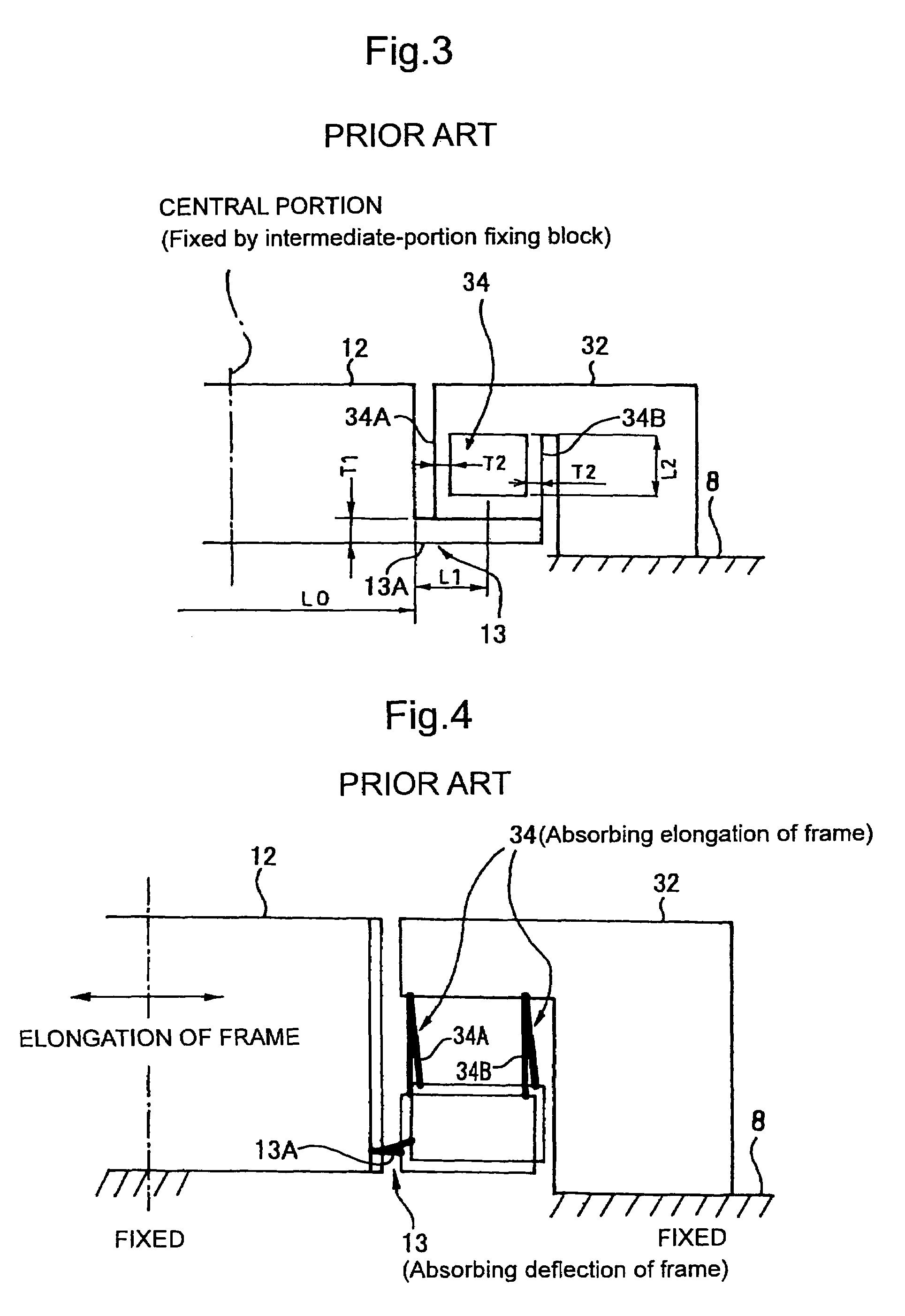
As a result, for example, the reduction of the sizes of the end-portion fixing block 32 in the cross-sectional direction in FIG. 3 and the reduction of the parts cost are difficult to achieve.
In addition, a unit type linear scale for a manual machine tool is required to be used in relatively severe temperature environments.

Method used


Image

  • Elastic fixture and attachment method for length measuring apparatus
  • Elastic fixture and attachment method for length measuring apparatus
  • Elastic fixture and attachment method for length measuring apparatus

Examples


Embodiment Construction

[0029]Various embodiments of this invention will be hereinafter described in detail with reference to the drawings.

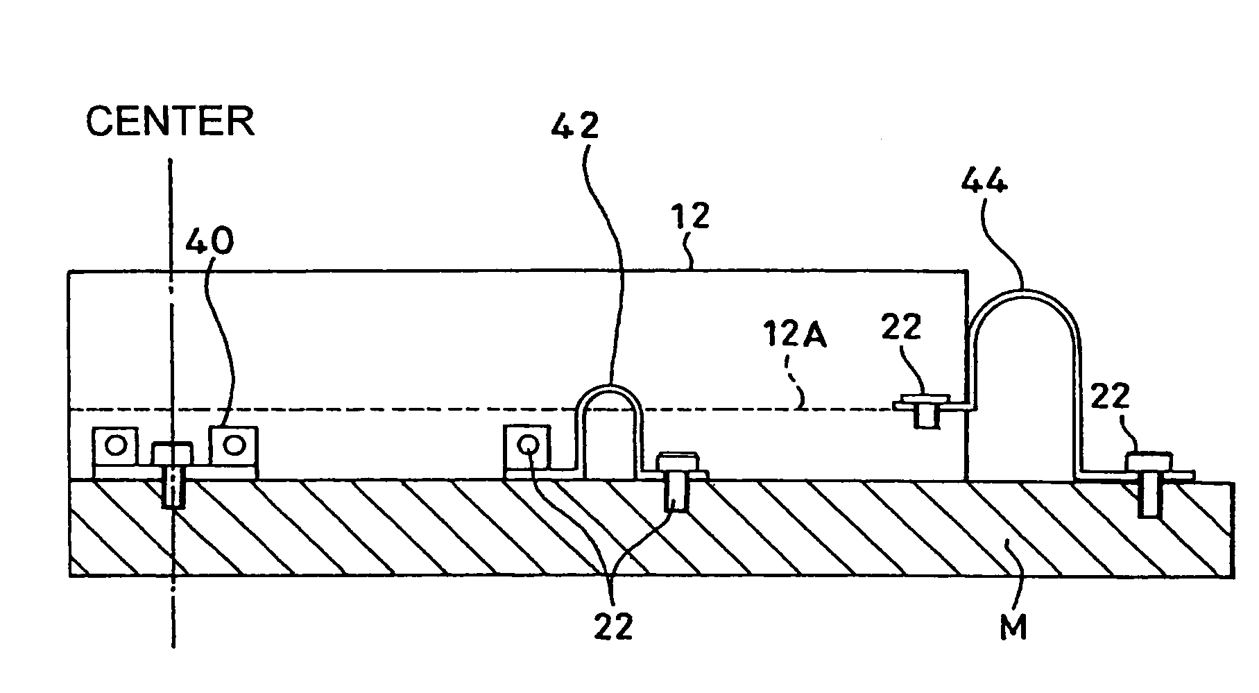
[0030]FIG. 5 schematically shows a state in which a unit type linear scale (a length measuring apparatus) 10 is attached to a mating machine (an object to be measured) M by use of elastic fixtures of the embodiment of the present invention.

[0031]In this embodiment, a permanent fixture 40 formed by a sheet-metal part is disposed at the center of an aluminum frame 12 for permanent fixation. Also, a curved beam 42 or 44 made of a sheet metal is disposed at each of a plurality of locations, including both ends of the frame 12 (only one end is shown in FIG. 5), in the lengthwise direction of the frame 12.

[0032]FIGS. 6A to 6C are schematic perspective views of the sheet-metal parts 40, 42, and 44, respectively. The holes represented by a circle in FIGS. 6A to 6C are tapped holes. The permanent fixture 40 and the curved beam fixture 42 are made of a sheet-metal part. One end o...


PUM


Abstract

An elastic fixture which is employed for attaching a length measuring apparatus to an object to be measured having a different linear expansion coefficient therefrom. The elastic fixture is elastically deformable in the lengthwise direction of the length measuring apparatus. The elastic fixture includes a sheet-metal curved beam having one end fixedly attached to the length measuring apparatus and the other end fixedly attached to the object to be measured. The sizes and the machining accuracy of the elastic fixture are less restricted, and the elastic fixture can be manufactured easily. In addition, the elastic fixture is applicable to relatively severe temperature environments in a manual machine tool or the like. Further, the sizes and the cost of the elastic fixture can be reduced as compared with a parallel spring mechanism.

Description

CROSS-REFERENCE TO RELATED APPLICATION[0001]The disclosure of Japanese Patent Application No. 2004-212103 filed Jul. 20, 2004 including specification, drawings and claims is incorporated herein by references in its entirety.BACKGROUND OF THE INVENTION[0002]1. Field of the Invention[0003]The present invention relates to an elastic fixture and an attachment method for mounting a length measuring apparatus on an object to be measured having a different linear expansion coefficient from that of the apparatus. In particular, the present invention relates to an elastic fixture for a length measuring apparatus which is suitably employed in a unit type linear scale fixedly attached, along with a main scale made of glass contained in a frame made of aluminum, to a machine body made predominantly of iron, and which can absorb large thermal stresses caused by the difference in linear expansion coefficients. The present invention also relates to a method of attaching a length measuring apparatu...

Claims


Application Information

Patent Timeline
Patent Type & Authority Patents(United States)
IPC IPC(8): G01B11/00G01D21/00
CPCG01B5/0014G01D5/34707G01D5/34753G01D11/30
Inventor KAWADA, HIROAKIMORI, HIROATSU
Owner MITUTOYO CORP
Learn More