
Power supply for an electric meter having a high-voltage regulator that limits the voltage applied to certain components below the normal operating input voltage

a technology of high-voltage regulator and power supply, which is applied in the direction of power conversion system, dc-dc conversion, instruments, etc., can solve the problems of significant design challenges, physical largeness of devices, and load inability to make us

Active Publication Date: 2008-04-08
ELSTER ELECTRICTY LLC
View PDF176 Cites 39 Cited by
  • Summary
  • Abstract
  • Description
  • Claims
  • Application Information

AI Technical Summary

Problems solved by technology

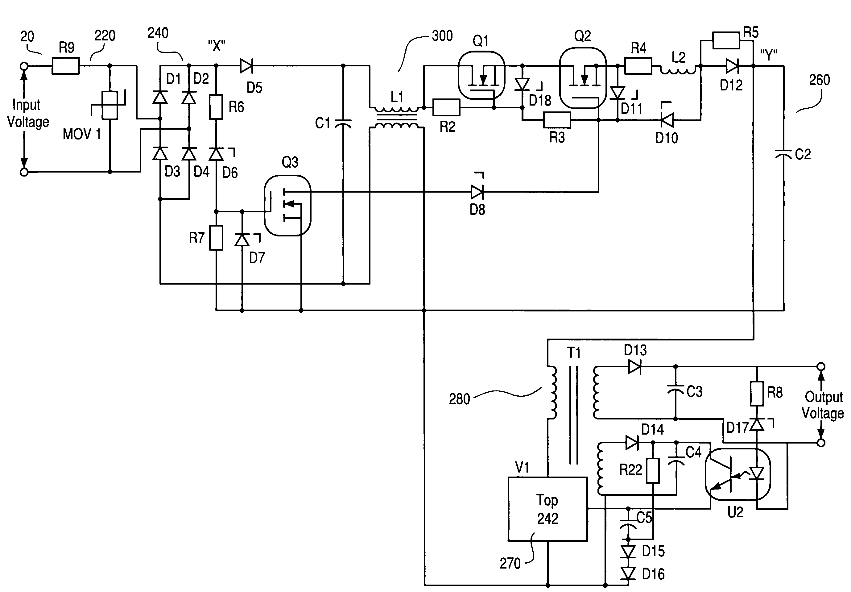
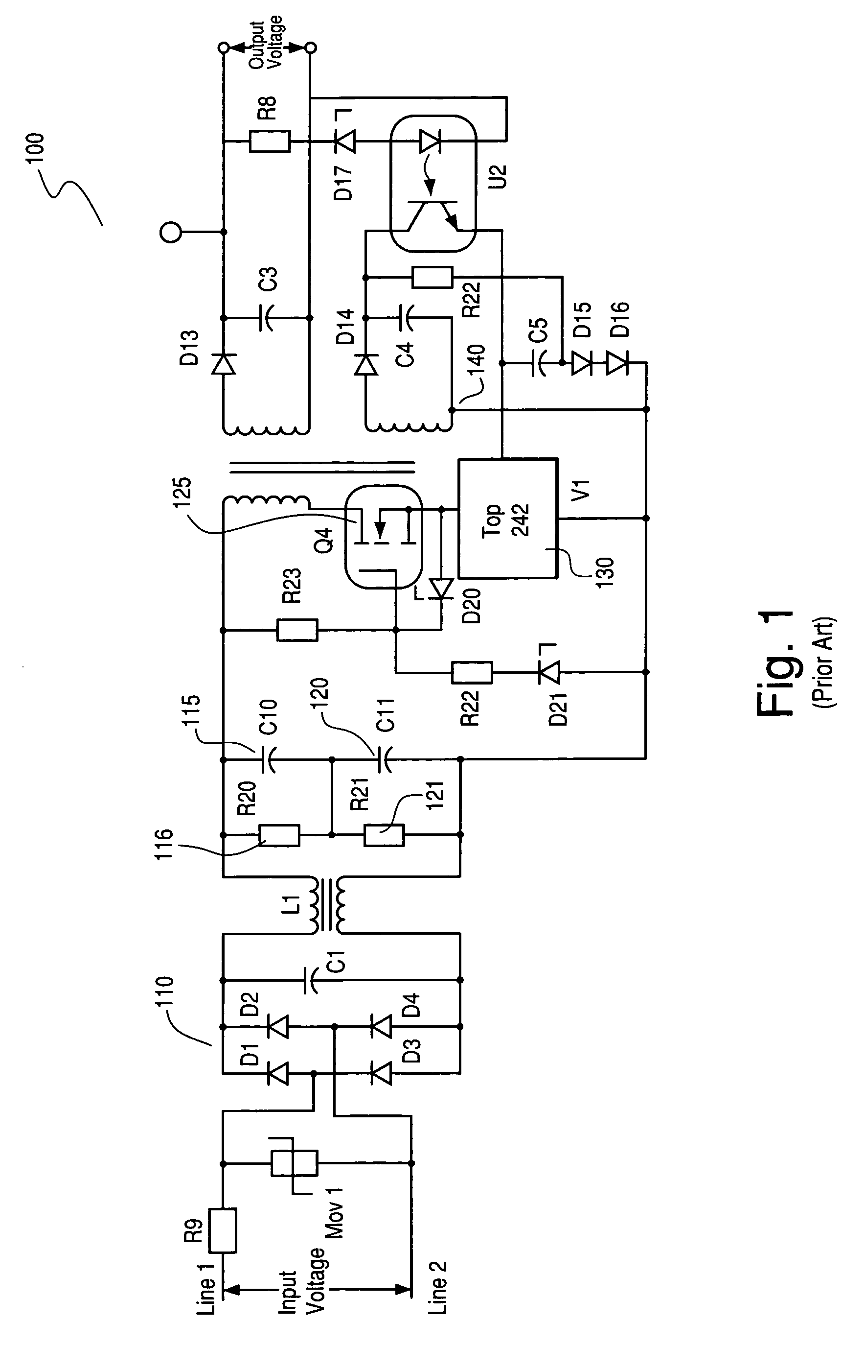
This large voltage range creates significant design challenges for power supply components such as devices that store electrical charge 115, 120, switching device 130, and switching transformer 140.
Because of the potential high voltages, the devices must be physically large.
Therefore power supply 100 has more energy available at high input voltages but loads cannot make use of it.
Designing switching transformer 140 to operate over this wide voltage range is also difficult.

Method used


Image

  • Power supply for an electric meter having a high-voltage regulator that limits the voltage applied to certain components below the normal operating input voltage
  • Power supply for an electric meter having a high-voltage regulator that limits the voltage applied to certain components below the normal operating input voltage
  • Power supply for an electric meter having a high-voltage regulator that limits the voltage applied to certain components below the normal operating input voltage

Examples


Embodiment Construction

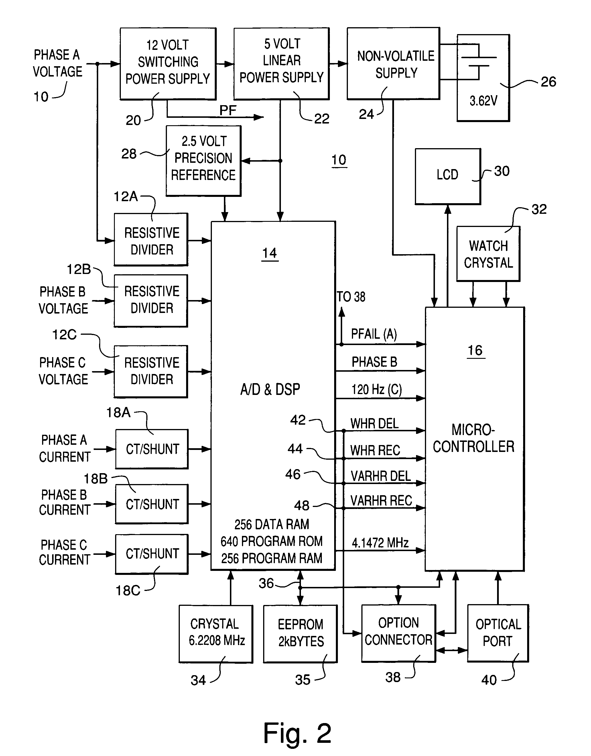
[0018]FIG. 2 is a block diagram of an electric meter 10. As shown in FIG. 2, meter 10 is shown to include three resistive voltage divider networks 12A, 12B, 12C; a first processor—an ADC / DSP (analog-to-digital converter / digital signal processor) chip 14; a second processor—a microcontroller 16 which in the preferred embodiment is a Mitsubishi Model 50428 microcontroller; three current sensors 18A, 18B, 18C; a 12 V switching power supply 20 that is capable of receiving inputs in the range of 46-530 alternating current voltage (VAC); a 5 V linear power supply 22; a nonvolatile power supply 24 that switches to a battery 26 when 5 V supply 22 is inoperative; a 2.5 V precision voltage reference 28; a liquid crystal display (LCD) 30; a 32.768 kHz oscillator 32; a 6.2208 MHz oscillator 34 that provides timing signals to chip 14 and whose signal is divided by 1.5 to provide a 4.1472 MHz clock signal to microcontroller 16; a 2 kbyte EEPROM 35; a serial communications line 36; an option conne...


PUM


Abstract

Disclosed is an invention relating to a power supply for use in an apparatus for measuring electrical energy, comprising, in one embodiment, a first switching device, a device for storing electrical charge in electrical connection with the first switching device, a second switching device in electrical connection with the device for storing electrical charge, a first device for controlling the flow of current in electrical connection with the second switching device, and a third switching device in electrical connection with the first device for controlling the flow of current, wherein the first device for controlling the flow of current enables an input voltage to be applied to the second switching device when the input voltage is below a predetermined amount, and enables the input voltage to be applied to the second and third switching devices when the input voltage is above the predetermined amount.

Description

FIELD OF THE INVENTION[0001]The invention relates generally to the field of electric utility meters. More particularly, the invention relates to switching power supplies within electric utility meters.BACKGROUND OF THE INVENTION[0002]Electric utility companies and power consuming industries have in the past employed a variety of approaches to metering electrical energy. Typically, a metering system monitors power lines through isolation and scaling components to derive polyphase input representations of voltage and current. These basic inputs are then selectively treated to determine the particular type of electrical energy being metered. Because electrical uses can vary significantly, electric utility companies have requirements for meters configured to analyze several different nominal primary voltages, the most common of which are 96, 120, 208, 240, 277 and 480 volts, root mean squared (RMS).[0003]Electric utility meters employing electronic components instead of electromechanica...

Claims


Application Information

Patent Timeline
Patent Type & Authority Patents(United States)
IPC IPC(8): H02H7/122H01G2/12H02M3/335
CPCG05F5/00H02M3/28H02M2001/0045H02M1/0045
Inventor SHUEY, KENNETH C.
Owner ELSTER ELECTRICTY LLC
Learn More