
Remote center range finder

a remote center and range finder technology, applied in the field of remote center range finders, can solve the problems of inaccurate distance measurement, device not directly measuring ssd, and significant variations in radiation treatment dose to the tumor, and achieve the effect of efficient calibration and highly accurate distance measuremen

Active Publication Date: 2008-04-08
SIEMENS MEDICAL SOLUTIONS USA INC
View PDF3 Cites 10 Cited by
  • Summary
  • Abstract
  • Description
  • Claims
  • Application Information

AI Technical Summary

Benefits of technology

[0006]The present invention is directed to a system and method for measuring the distance between a first point spaced away from a surface of an object and a second point on a surface of an object along an axis extending through the first point and the second point. The system and method are particularly suitable for use in radiation oncology for measuring the distance of a radiation source to the body of a patient (e.g., the source-to-skin-distance (SSD)) during radiation treatment. The present invention is further directed to a method for efficiently calibrating such distance measuring systems so that highly accurate distance measurements may be obtained.

Problems solved by technology

Unfortunately, healthy tissue and organs are often in the path of a radiation beam during radiation treatment, and may be damaged by the radiation.
Accordingly, small variations in SSD measurement may cause significant variations in the radiation treatment dose to the tumor.
Current treatment plans are designed under the assumption that SSD measurement errors may occur that result in misdelivery of radiation.
However, these devices do not directly measure SSD and may not be accurate.

Method used


Image

  • Remote center range finder
  • Remote center range finder
  • Remote center range finder

Examples


Embodiment Construction

[0022]Reference will now be made in detail to the presently preferred embodiments of the invention, examples of which are illustrated in the accompanying drawings.

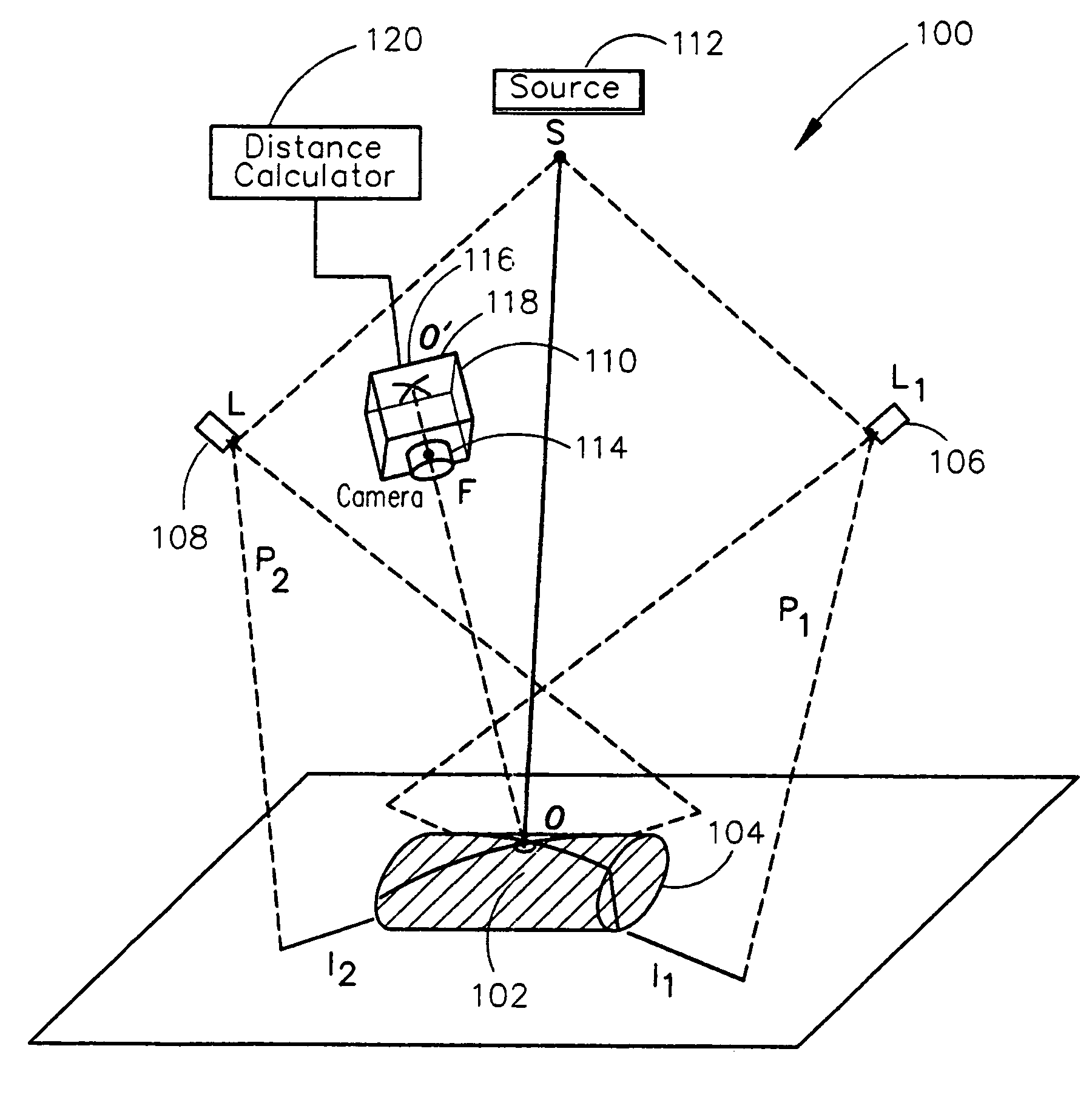
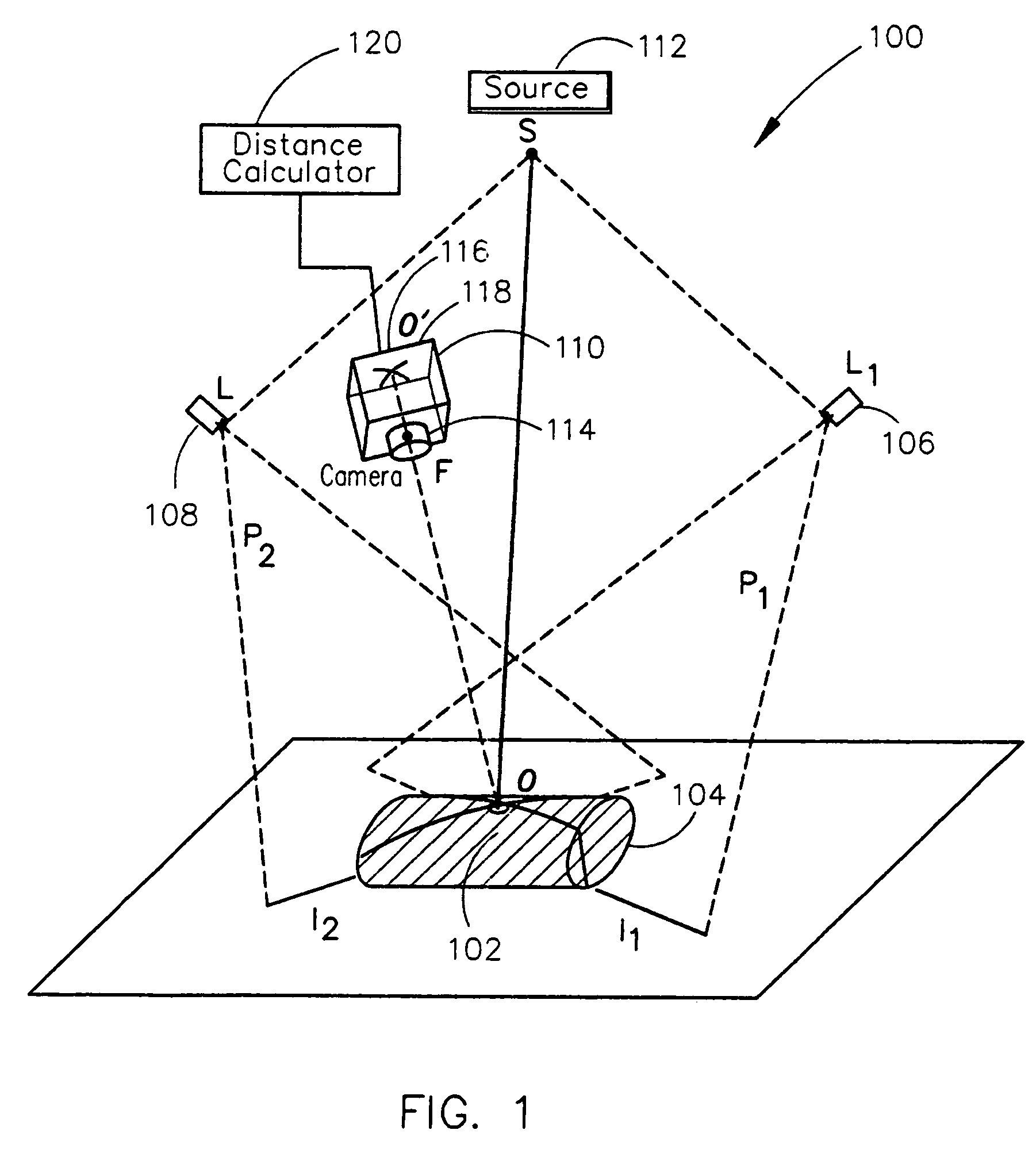
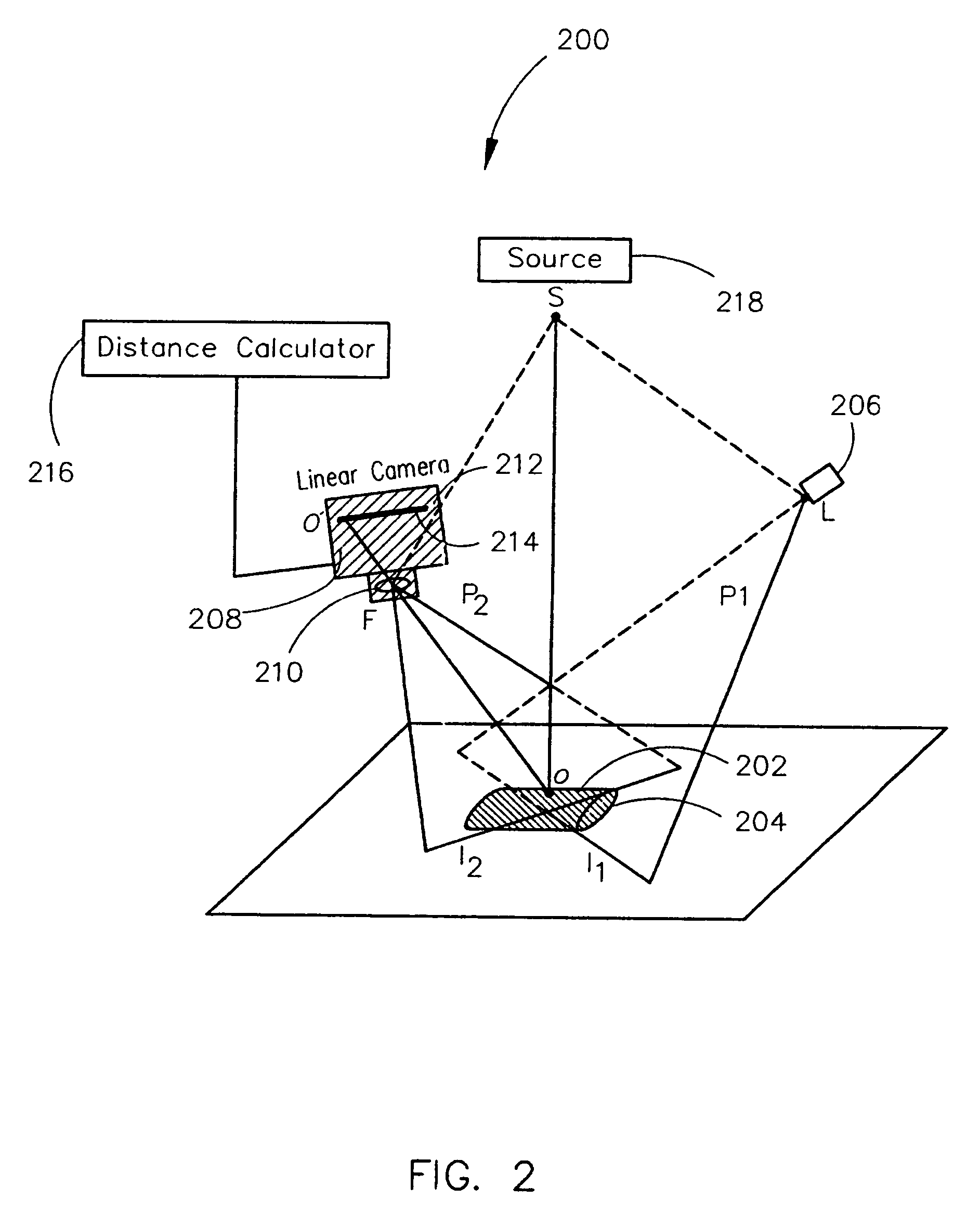
[0023]FIG. 1 illustrates a system 100 for measuring the distance from a first point S spaced away from a surface 102 of an object 104 to a second point O on the surface 102 of the object 104 such that second point O is on a principle axis originating from the point S in accordance with the present invention. As shown in FIG. 1, the system 100 includes two or more projection assemblies 106 and 108 which project planes of light that intersect the surface 102 of the object 104 to form light stripes on the surface 102. An imaging device 110 detects the position of the second point O by sensing the intersection of the light stripes at the second point O. The distance between the first point S and the second point O may then be determined from the detected position of the second point O.

[0024]In the specific embodiment shown in ...


PUM


Abstract

A system for measuring the distance from a first point spaced away from a surface of an object to a second point on a surface of the object along an axis extending through the first and second points includes one or more light projection assemblies for projecting light stripes onto the surface of the object so that the light stripes pass though the second point. An imaging device detects the position of the second point by sensing the light stripes at the second point. A distance calculator may then calculate the distance between the first point and the second point using the position of the second point detected by the imaging device. The system is calibrated using the cross-ratio of points detected along the axis by the imaging device.

Description

BACKGROUND OF THE INVENTION[0001]The present invention relates generally to apparatus and methods for measuring the distance between two points, and particularly, to a system and method for measuring the distance from a first point spaced away from a surface of an object to a second point on a surface of an object. More specifically, the present invention relates to a remote center range finder suitable for use in radiation oncology for measuring the distance of a radiation source to the body of a patient (i.e., source-to-skin-distance) during radiation treatment.[0002]Radiation oncology uses radiation therapy for the treatment of cancerous tumors in a patient's body. Conventional radiation therapy employs a linear accelerator or LINAC, which directs a beam of radiation (e.g., gamma ray or X-ray radiation) toward a cancerous tumor in a patient to deliver a predetermined dose of therapeutic radiation to the tumor. Unfortunately, healthy tissue and organs are often in the path of a ra...

Claims


Application Information

Patent Timeline
Patent Type & Authority Patents(United States)
IPC IPC(8): G01C3/00
CPCA61N5/1049G01B11/2513G01C3/08A61N2005/105A61N2005/1059
Inventor BANI-HASHEMI, ALI
Owner SIEMENS MEDICAL SOLUTIONS USA INC
Learn More