
Device for reversing rotational direction of a motor

a technology of rotating direction and motor, which is applied in the direction of portable power tools, rotary current collectors, dynamo-electric machines, etc., can solve the problems of reducing the wear of carbon brushes, and improving commutation. , to achieve the effect of stable electrical connection, convenient mounting and cost-effectiv

Active Publication Date: 2008-04-08
HILTI AG
View PDF12 Cites 13 Cited by
  • Summary
  • Abstract
  • Description
  • Claims
  • Application Information

AI Technical Summary

Benefits of technology

This solution achieves better commutation and reduced carbon brush wear, enhancing operational stability and cost-effectiveness by ensuring precise alignment and secure positioning of the carbon brushes.

Problems solved by technology

This, in turn, results in a better commutation and a smaller carbon brush wear.

Method used


Image

  • Device for reversing rotational direction of a motor
  • Device for reversing rotational direction of a motor
  • Device for reversing rotational direction of a motor

Examples


Embodiment Construction

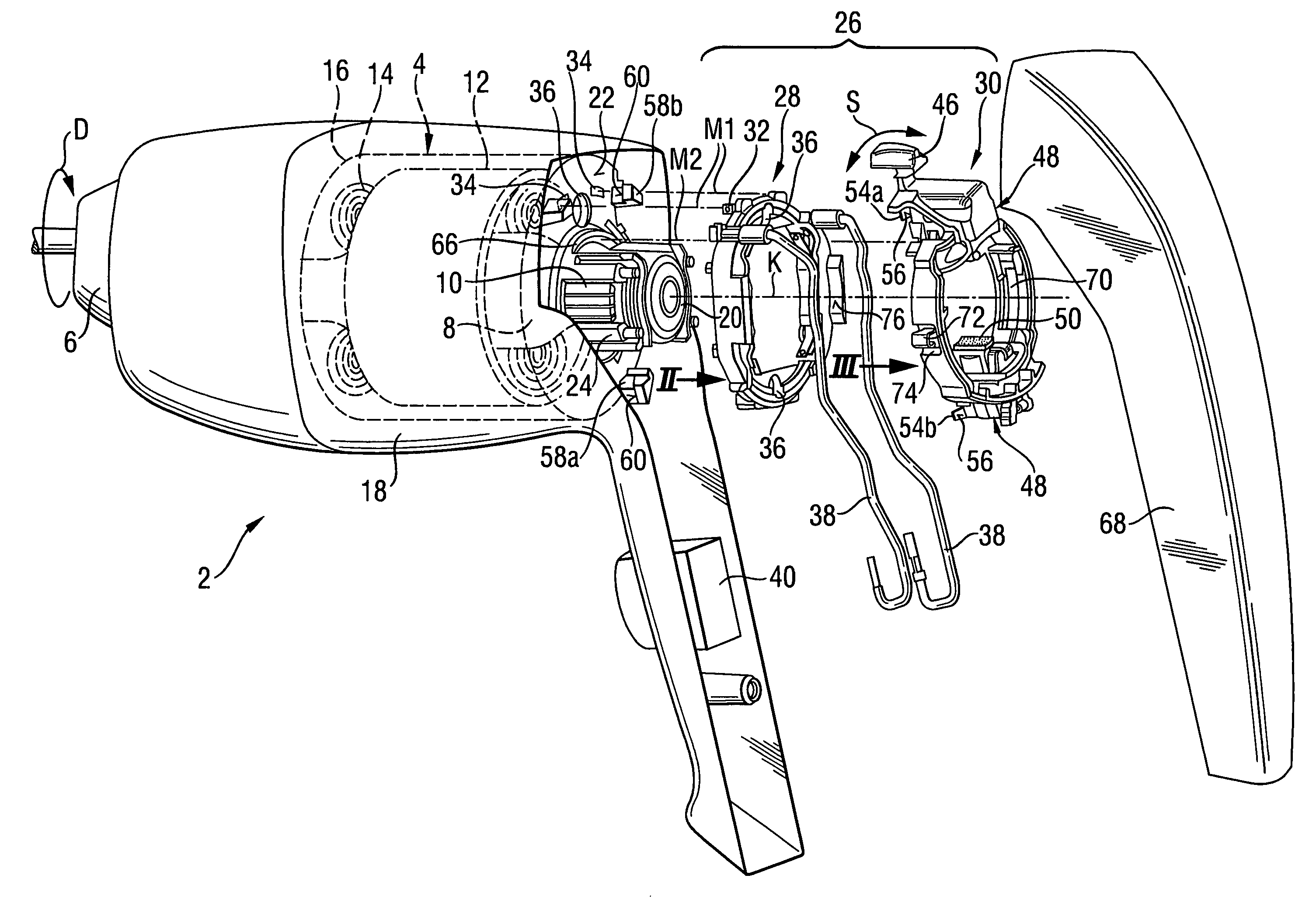
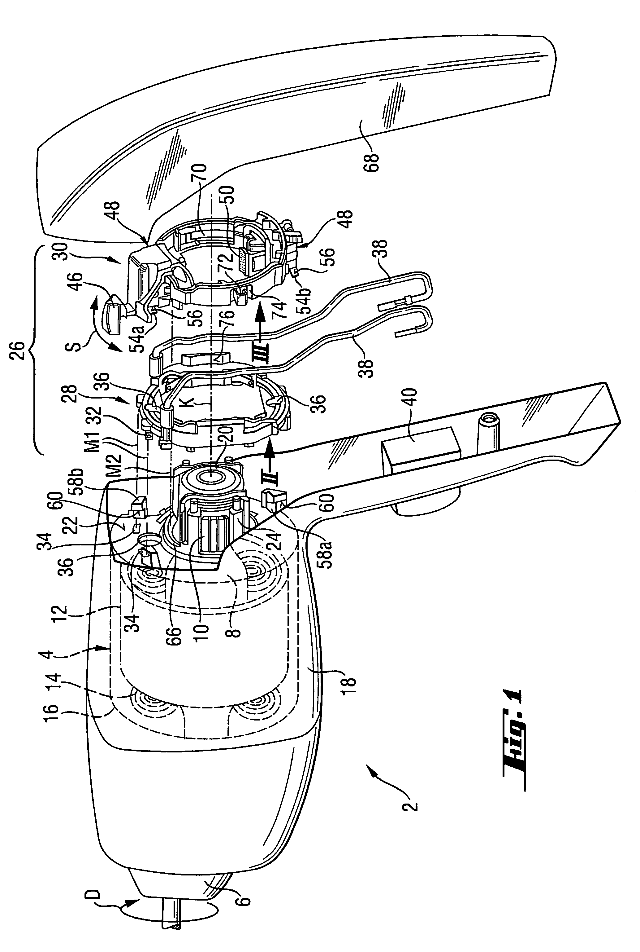
[0026]An electrical hand-held power tool 2 according to the present invention, e.g., combined drilling and screw-driving tool, which is shown in FIG. 1, has an electric motor 4 for driving a chuck 6 which is not shown in detail. The electric motor 4 has a rotor 8 and a commutator 10 connected with the rotor 8 for joint rotation therewith and rotatable about a commutator axis K.

[0027]Around the rotor 8, there is arranged a stator 12 with a stator winding 14. The stator 12 is located in a stator housing 16 shown with dash lines and which is fixedly secured in the housing 18 of the electrical hand-held power tool 2.

[0028]The commutator 10 is supported, at its end remote from the rotor 8, on a bearing block 20 that is itself supported on holding ribs 24 which project from an end side 22 of the stator housing 16.

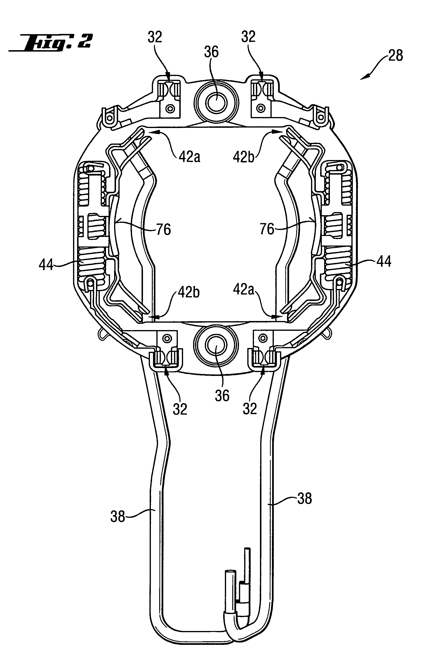
[0029]As shown in FIG. 2, during the assembly of the electrical hand-held power tool 2, a reversing device, which is generally designated with a reference numeral 26, is mounted ...


PUM


Abstract

An electrical hand-held power tool (2) includes an electric motor (4) with a stator (12), and a device (26) for reversing the rotational direction of the motor (4) and which has a contact carrier (28) fixedly securable on the stator housing with a releasable connection element and having field contacts (32) electrically connectable with the stator winding (14), and fixed contacts (42a, 42b) electrically connected with the field contacts (32), with the reversing device (26) also including a brush carrier (30) provided with carbon guides (48) and switching contacts (52a, 52b) electrically connected with the carbon guides (48) and electrically connectable with the fixed contacts (42a, 42b) of the contact carrier (28), the brush carrier (30) being rotatable relative to the contact carrier (28), and the stator housing (16) having an axial stop for the brush carrier (30).

Description

BACKGROUND OF THE INVENTION[0001]1. Field of the Invention[0002]The present invention relates to an electrical hand-held power tool with an electric motor having a stator housing and a device for reversing the rotational direction of the electric motor. The reversing device has a contact carrier fixedly securable on the stator housing with releasable connection means. On the contact carrier, there are provided field contact means for an electrical connection with the stator winding and fixed contacts means electrically connected with the field contact means. The reversing device further has a brush carrier rotatable relative to the contact carrier and on which there are provided two carbon guides and switching contact means electrically connected with carbon guides. The switching contact means are electrically connectable with fixed contacts of the contact carrier in respective rotational end positions.[0003]2. Description of the Prior Art[0004]Electrical hand-held tools of the type...

Claims


Application Information

Patent Timeline
Patent Type & Authority Patents(United States)
IPC IPC(8): H02K13/00
CPCH02K23/18B25F5/00H02K5/14H02K23/66H02K23/02
Inventor RIEDL, REINHARDHARTMANN, MARKUS
Owner HILTI AG
Learn More