
Inline bladder-type accumulator for downhole applications

a technology of accumulator and bladder, which is applied in the direction of liquid transfer devices, process and machine control, instruments, etc., can solve the problems of fluid shock wave, fluid shock wave, pressure pulsation, difficulty in removing, etc., and achieve the effect of improving the performance of a fluid hammer

Inactive Publication Date: 2008-04-08
SMITH INT INC
View PDF32 Cites 72 Cited by
  • Summary
  • Abstract
  • Description
  • Claims
  • Application Information

AI Technical Summary

Benefits of technology

The present patent is about an accumulator for downhole operations that can improve the performance of a fluid hammer. The accumulator has a housing with an anti-extrusion device that can open or close the fluid compartment from the hydraulic system based on pressure fluctuations. The accumulator can also have a flow diverter to direct fluid towards the gas compartment. The accumulator can increase the delivered horsepower from the fluid hammer by at least 25%. The method of using the accumulator involves connecting it to the hydraulic system and controlling the anti-extrusion device to regulate fluid communication. The accumulator can also absorb pressure fluctuations and deliver hydraulic energy to the fluid hammer. Overall, the accumulator can improve the performance of the fluid hammer in drilling and wellbore operations.

Problems solved by technology

Air and fluid-driven hammer bits are both effective in some respects, but each type presents several challenges.
For example, hammer drilling with air sometimes results in difficulty removing cuttings, and hammer drilling with fluid results in the need to dissipate fluid shocks.
However, the driving fluid is continuously being supplied to the hammer, such that during those brief moments when the piston is not moving, a fluid shock wave, or pressure pulsation, results.
With respect to a fluid hammer, fluid shock waves can be destructive to the hammer itself, to nearby components, and / or to the drill string.
These pressure pulsations also represent a loss of hydraulic energy that could be made available to the fluid hammer.
First, the mass of the piston itself slows the response time of the accumulator to pressure spikes or fluctuations in the hydraulic circuit, which is an impediment when the accumulator must respond quickly.
Second, the sealing elements disposed between the piston and the housing are exposed to high differential pressures, high velocities, and—in the case of downhole drilling tools—abrasive fluids, and therefore do not have a long operational life.
Bladder-type accumulators, although significantly more responsive than piston-type accumulators due to their lower mass, also have some operational limitations.
First, some bladder-type accumulators are not inline, meaning the accumulator is not connected axially to the hydraulic system piping.
This type of accumulator necessarily requires more radial space than an inline accumulator, which may make it unsuitable for use within a well bore where space is limited.
Second, many bladder-type accumulators have anti-extrusion devices that are attached to and move with the bladder, thereby adding mass to the moveable bladder and increasing the response time of the accumulator to pressure fluctuations in the hydraulic system.
Third, some bladder-type accumulators have non-moving anti-extrusion devices, such as sleeves with perforations through which the fluid must pass in order to enter or exit the bladder.
However, small perforations limit the response time of the accumulator because the fluid flowing into the bladder must pass through such perforations.
In addition, openings like perforations in a sleeve produce turbulence or disturbances in the fluid that can erode the sleeve over time.

Method used


Image

  • Inline bladder-type accumulator for downhole applications
  • Inline bladder-type accumulator for downhole applications
  • Inline bladder-type accumulator for downhole applications

Examples


second embodiment

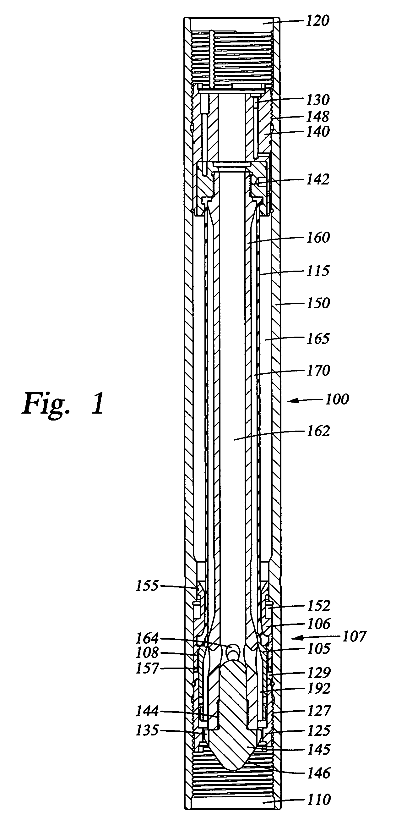
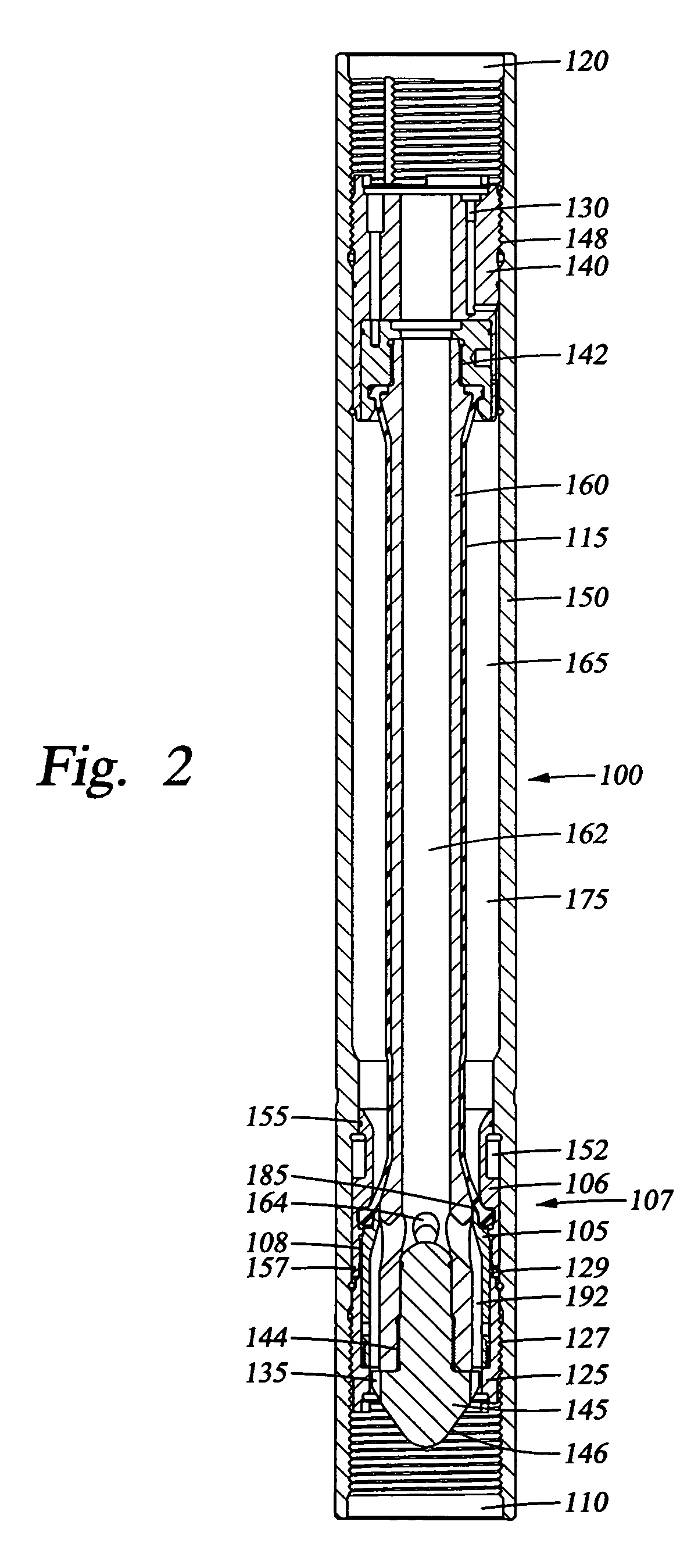
[0042]The anti-extrusion device in accumulator 100 is a pressure actuated two-part piston 107, but the anti-extrusion device of an inline bladder-type accumulator may take different forms. FIG. 4 depicts an inline bladder-type accumulator 200 in the downhole configuration. The accumulator 200 utilizes a pressure actuated ported sliding mandrel 205 as the anti-extrusion device. The inline bladder-type accumulator 200 comprises the sliding mandrel 205 with an internal flow bore 202 and ports 210 extending through the wall thereof, a spring housing 215 forming a spring chamber 260 that encloses springs 220, and a flexible elastomeric bladder 115 retained by a bladder retainer 240, all enclosed within a cylindrical housing 150. The bladder 115 separates a gas compartment 165, located between the outer surface of the bladder 115 and the inner surface of the housing 150, from a fluid compartment 170, located between the inner surface of the bladder 115 and the outer surface of the mandrel...

third embodiment

[0045]In other embodiments, the routing of flow through the accumulator may also vary. FIGS. 1-4 depict “flow-through” accumulators 100, 200 with flow bores 162, 202 that direct fluid flow through the center of the accumulator 100, 200, and that flow is diverted to an externally located bladder 115. FIG. 5, on the other hand, depicts an inline bladder-type accumulator 300, namely a “flow-around” accumulator 300, wherein the fluid 180 flows along an external flow path 302, and that flow is diverted to an internally located bladder 115.

[0046]FIG. 5 depicts the accumulator 300 in the downhole configuration. Accumulator 300 comprises a sliding cylinder 351 with ports 353 extending through a wall thereof, a bladder support mandrel 345 connected via threads 347 to a mandrel support ring 340 comprising flow ports 304 leading into the flow path 302, a cavity 315 disposed between the sliding cylinder 351 and the bladder support mandrel 345 wherein springs 220 reside, and a flexible elastomer...

fourth embodiment

[0049]Referring now to FIG. 6, an inline, flow-through, bladder-type accumulator 400 is depicted that utilizes an anti-extrusion device similar to the accumulator 100 shown in FIGS. 1-3, namely a piston 407 consisting of two sub-components, an upper piston 406 and a lower piston 405. However, in accumulator 400, the piston 407 is bound from further movement at the downstream end by a retainer ring 425. FIG. 6 shows the accumulator 400 in the precharged configuration. The accumulator 400 comprises a cylindrical mandrel 160 with an internal flow bore 162, a flexible elastomeric bladder 115 surrounding the mandrel 160, a piston 407 with a seal 155, a threaded sleeve 430 to which a valve may be connected to inject nitrogen, and a retainer ring 425, all enclosed within a cylindrical housing 150. The bladder 115 resides between two compartments, a gas compartment 165, shown precharged with nitrogen 175, and a fluid compartment 170 that has fluid 180 therein in the position shown in FIG. 6...


PUM


Abstract

An accumulator comprises a housing connected to a hydraulic system, an elastomeric bladder separating a gas compartment from a fluid compartment, and an anti-extrusion device. A method for operating an accumulator comprises connecting the accumulator to a hydraulic system, injecting an inert gas into a gas compartment to a precharge pressure, moving an anti-extrusion device to prevent a bladder from extruding into the hydraulic system, running the accumulator and the hydraulic system downhole, moving the anti-extrusion device to allow fluid communication between the hydraulic system and a fluid compartment, generating pressure fluctuations within the hydraulic system, and expanding or contracting the bladder in response to the pressure fluctuations without moving the anti-extrusion device. A method of improving fluid hammer performance comprises connecting the fluid hammer to an accumulator that produces a greater delivered horsepower from the fluid hammer as compared to a baseline horsepower when operating without the accumulator.

Description

CROSS-REFERENCE TO RELATED APPLICATIONS[0001]None.STATEMENT REGARDING FEDERALLY SPONSORED RESEARCH OR DEVELOPMENT[0002]Not applicable.REFERENCE TO A MICROFICHE APPENDIX[0003]Not applicable.FIELD OF THE INVENTION[0004]The present invention relates generally to various embodiments of an inline bladder-type accumulator for use in high pressure downhole applications, and methods of designing such accumulators for optimized performance. More particularly, the present invention relates to quick-acting, inline bladder-type accumulators with anti-extrusion capability for high charging pressures, and methods of employing such accumulators in downhole applications to absorb fluid shocks and to store hydraulic energy.BACKGROUND[0005]Downhole drilling may be performed with many different types of drill bits, including hammer bits that are operated with air or an incompressible fluid, such as water or drilling mud. Air and fluid-driven hammer bits are both effective in some respects, but each ty...

Claims


Application Information

Patent Timeline
Patent Type & Authority Patents(United States)
IPC IPC(8): F16L55/04
CPCE21B4/14F15B1/027F15B1/165F15B1/18F15B2201/3152Y10T137/3118E21B41/00F15B1/024F15B1/20
Inventor UNDERWOOD, LANCE D.SWADI, SHANTANU N.
Owner SMITH INT INC
Learn More