
Method for the closed-loop speed control of an internal combustion engine-generator unit

a technology of internal combustion engine and closed loop speed control, which is applied in the direction of electric controllers, electric control, instruments, etc., can solve the problems of loss of dynamic range, inability to operate with the optimum parameters of starting operation, and most difficult automatic control of internal combustion engine. , to achieve the effect of small extra cos

Active Publication Date: 2008-04-01
ROLLS ROYCE SOLUTIONS GMBH
View PDF10 Cites 15 Cited by
  • Summary
  • Abstract
  • Description
  • Claims
  • Application Information

AI Technical Summary

Benefits of technology

The present invention is a method for controlling an internal combustion engine-generator unit during the starting operation. The method uses a second set of parameters when the coupling has engaged, allowing for a smoother starting operation. The second set of parameters has higher values for certain controller parameters, such as the second proportional coefficient, second rate-action time, and second integral-action time. The method can be used in an electronic engine-control unit without needing to change hardware, reducing costs. Overall, the method improves the starting operation of the engine-generator unit.

Problems solved by technology

Automatic control of the internal combustion engine is most difficult when the engine is uncoupled, i.e., the stability reserve is then at its lowest.
For all internal combustion engines that are operated with a generator, this means a loss of dynamic range.
In the case of internal combustion engines that power systems with a very large moment of inertia, this is unsatisfactory.
For the aforementioned example of a coupling that does not engage until during the run-up of the engine, this means that the starting operation is not being operated with the optimum parameters.

Method used


Image

  • Method for the closed-loop speed control of an internal combustion engine-generator unit
  • Method for the closed-loop speed control of an internal combustion engine-generator unit
  • Method for the closed-loop speed control of an internal combustion engine-generator unit

Examples


Embodiment Construction

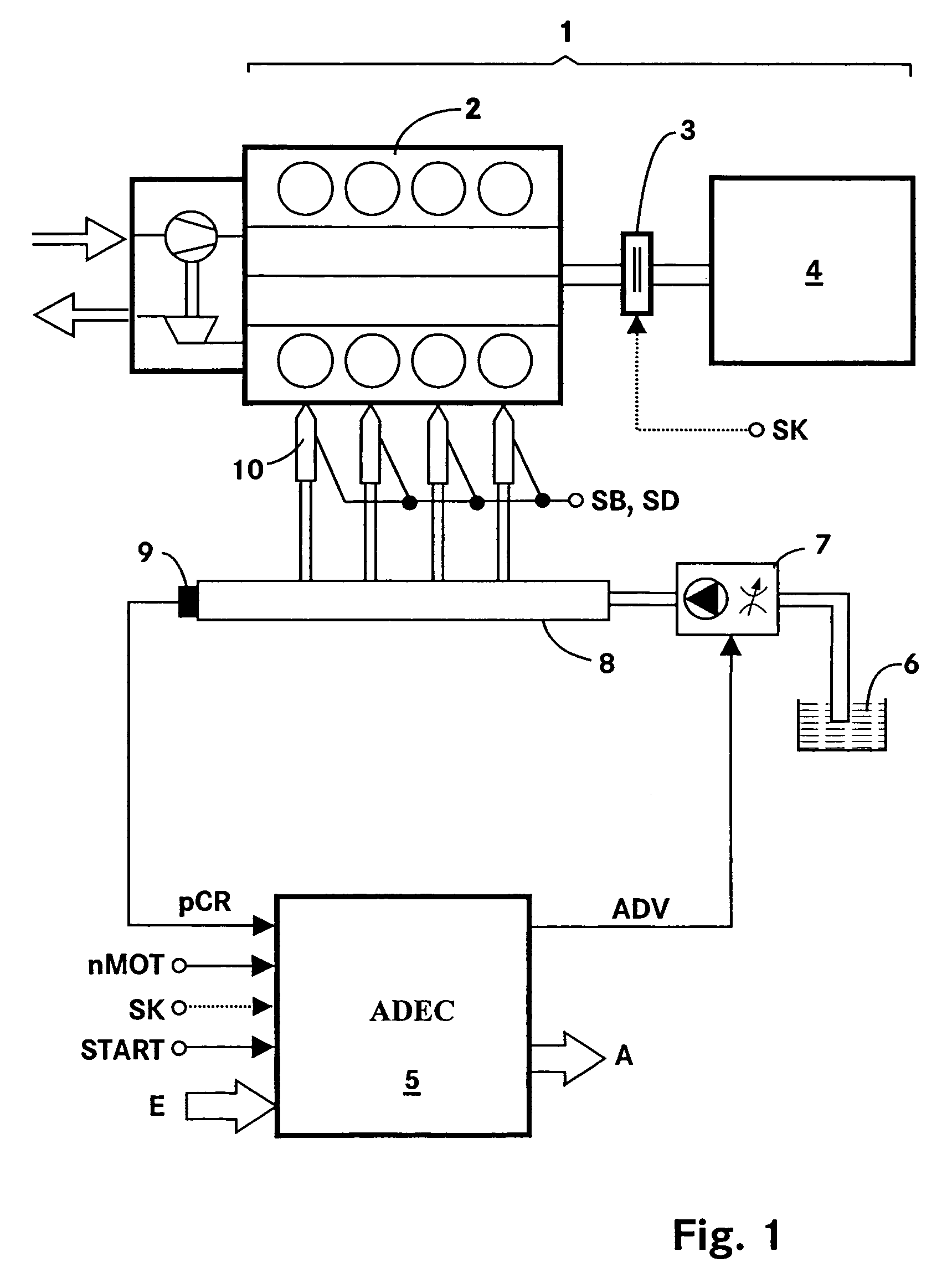
[0015]FIG. 1 shows a system diagram of the total system of an internal combustion engine-generator unit 1. An internal combustion engine 2 drives a generator 4 via a shaft. In the illustrated internal combustion engine 2, the fuel is injected by a common-rail injection system. This injection system comprises the following components: pumps 7 with a suction throttle for conveying the fuel from a fuel tank 6, a rail 8 for storing the fuel, and injectors 10 for injecting the fuel from the rail 8 into the combustion chambers of the internal combustion engine 2.

[0016]The operation of the internal combustion engine 2 is automatically controlled by an electronic control unit (ADEC) 5. The electronic control unit 5 contains the usual components of a microcomputer system, for example, a microprocessor, interface adapters, buffers, and memory components (EEPROM, RAM). The relevant operating characteristics for the operation of the internal combustion engine 2 are applied in the memory compone...


PUM


Abstract

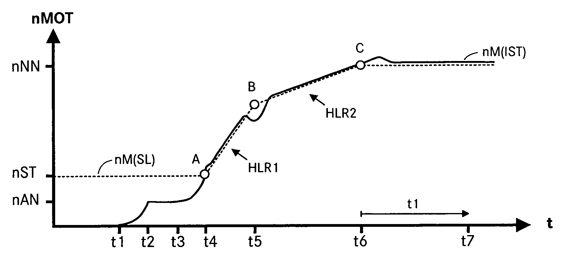
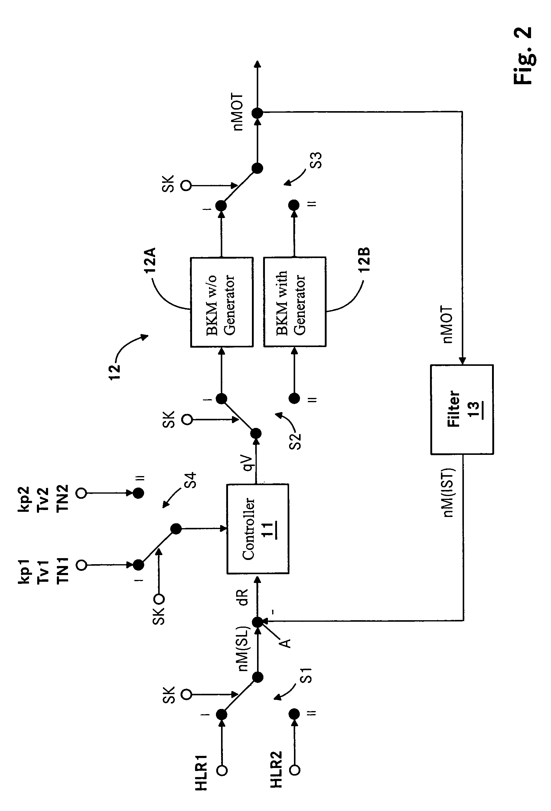
A method for the closed-loop speed control of an internal combustion engine-generator unit with a coupling, in which method, when the engagement of the coupling is detected, a change is made from a first set of parameters to a second set of parameters. In the second set of parameters, a second run-up ramp is set, which determines the presetting of the set speed, and second controller parameters are set as the determining factors for computing controller components of a speed controller.

Description

BACKGROUND OF THE INVENTION[0001]The invention concerns a method for the closed-loop speed control of an internal combustion engine-generator unit.[0002]Emergency standby installations are started in an uncoupled state when the public power supply system fails and are coupled with the generator, at the latest, when a rated speed is attained. A system of this type will be referred to hereinafter as an internal combustion engine-generator unit. In the case of electromagnetic couplings, the coupling process is initiated by a coupling signal. Couplings of this type usually already engage during the run-up of the internal combustion engine.[0003]When the coupling engages, the total moment of inertia of the system experiences a sharp change. The internal combustion engine has a moment of inertia of about 20 kgm2. The generator with induction coupling has a moment of inertia of about 360 kgm2. After the power failure, the induction coupling supplies the necessary energy to the system until...

Claims


Application Information

Patent Timeline
Patent Type & Authority Patents(United States)
IPC IPC(8): F02N11/00F02P9/00F02D29/06F02D41/06F02D41/14F02D41/30F02D43/00F02D45/00G05B11/42G05D13/02H02P9/00
CPCF02D31/007F02D41/022F02D41/2422H02P9/04F02D2041/1409F02D2041/1422F02D29/06F02D41/14F02D41/1401G05B11/42G05D13/02
Inventor DOLKER, ARMINSCHAFER, KLAUS
Owner ROLLS ROYCE SOLUTIONS GMBH
Learn More