
Method for operating a flex fuel conversion system

a fuel conversion and fuel injection technology, applied in the field of vehicles, can solve the problems of not being able to produce a flex fuel vehicle, aftermarket manufacturers generally not being able to produce flex fuel vehicles, and older vehicles generally not having the proper equipment to allow, so as to reduce hydrocarbon, carbon monoxide and nitrogen oxide emissions, and be easy to install.

Inactive Publication Date: 2008-03-25
SREMAC MILAN J +1
View PDF21 Cites 9 Cited by
  • Summary
  • Abstract
  • Description
  • Claims
  • Application Information

AI Technical Summary

Benefits of technology

Enables efficient operation of vehicles on various fuel mixes, increases horsepower and torque, reduces emissions, and is easy to install, while maintaining compliance with federal standards and allowing user-adjustable settings for performance applications.

Problems solved by technology

However, older vehicles generally do not contain the proper equipment to allow the older vehicle to operate upon ethanol, thus forcing the driver to utilize standard gasoline.
Due to federal emissions standards of preventing any individual from altering the factory installed fuel management system, aftermarket manufacturers have not been able to produce a flex fuel vehicle.
Factory fuel injectors are generally not designed to operate for long periods at the intense level required by the changes of the aftermarket manufactures to the fuel system.
In many instances, the vehicle “check engine” light may come on, due to the lean burn situation, thus often prompting the driver to fix their vehicle which can be expensive.

Method used


Image

  • Method for operating a flex fuel conversion system
  • Method for operating a flex fuel conversion system
  • Method for operating a flex fuel conversion system

Examples


Embodiment Construction

A. Overview

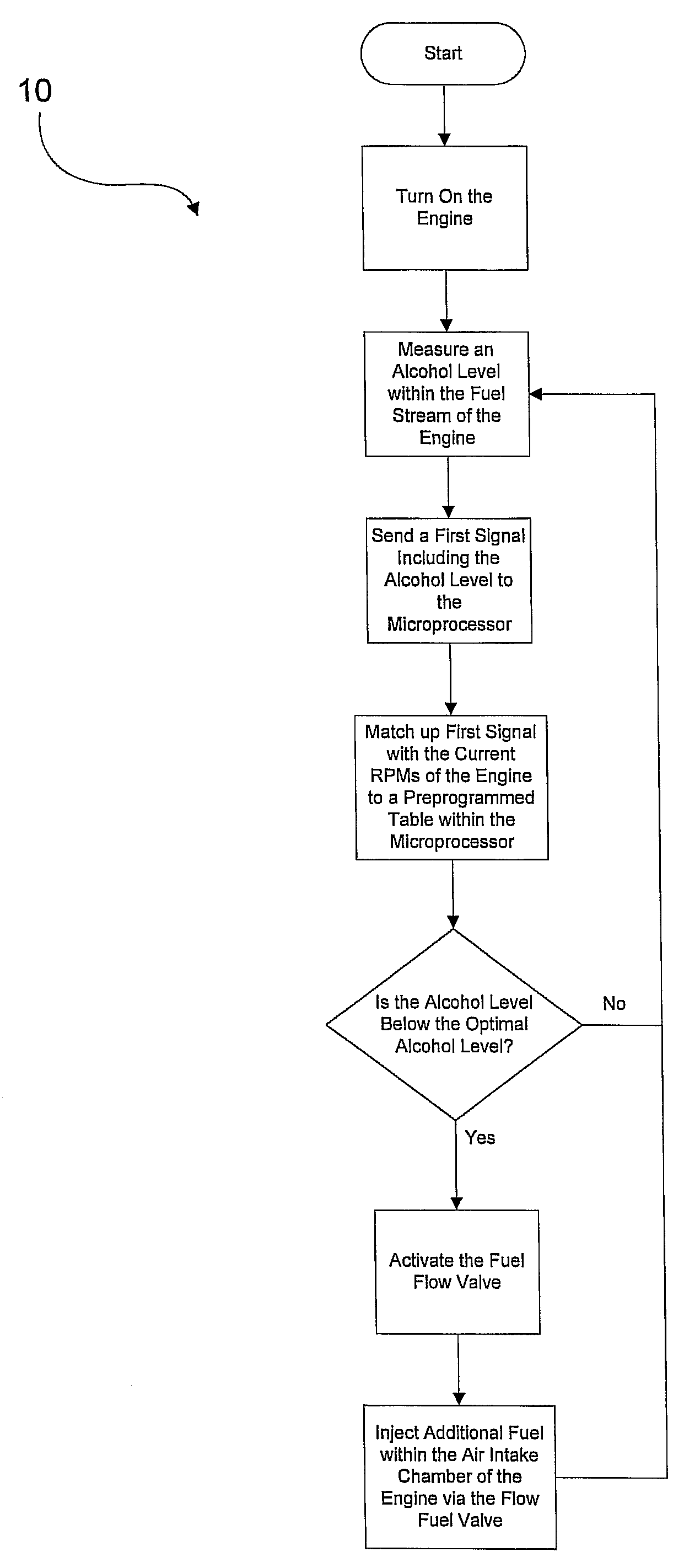
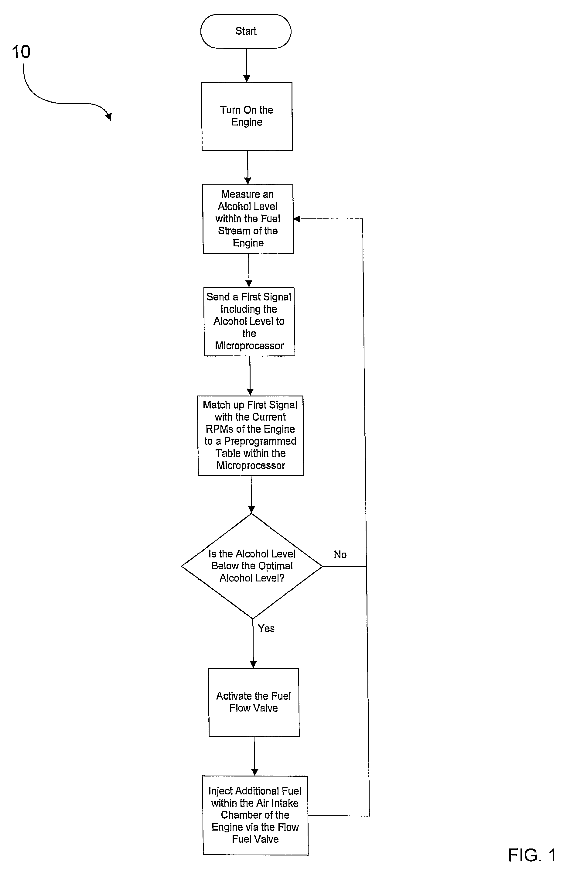
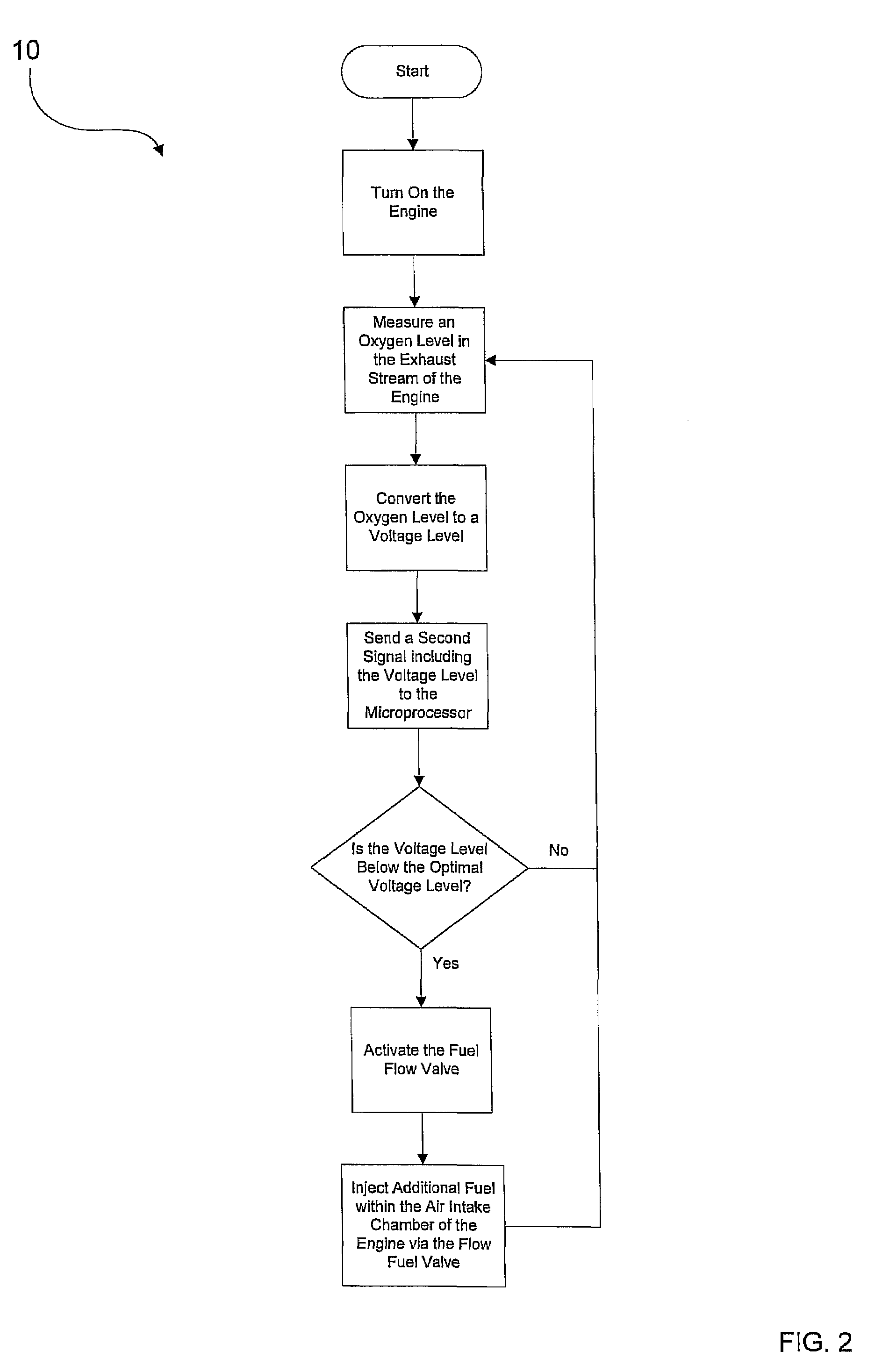
[0030]Turning now descriptively to the drawings, in which similar reference characters denote similar elements throughout the several views, FIGS. 1 through 4 illustrate a method for operating a flex fuel conversion system 10, which comprises providing a fuel sensor to measure a current alcohol level of fuel within a fuel stream of an engine; providing a microprocessor, wherein a first signal including the current alcohol level of the fuel is sent to the microprocessor from the fuel sensor and the current alcohol level is subsequently compared to an optimal alcohol level; providing a fuel flow valve(s), wherein an adjustment signal is sent to the fuel flow valve(s) from the microprocessor, wherein the adjustment signal informs the fuel flow valve(s) how much additional fuel of the fuel stream to inject within the engine or how much fuel of the fuel stream to prevent from entering the engine in order to achieve the optimal alcohol level and then adjusting the amount of fue...


PUM


Abstract

A method for operating a flex fuel conversion system for efficiently providing an aftermarket fuel delivery system which allows a vehicle to be operated on gasoline, ethanol or any combination of gasoline and ethanol. The a method for operating a flex fuel conversion system generally includes providing a fuel sensor to measure a current alcohol level of fuel within a fuel stream of an engine; providing a microprocessor, wherein a first signal including the current alcohol level of the fuel is sent to the microprocessor from the fuel sensor and the current alcohol level is subsequently compared to an optimal alcohol level; providing a fuel flow valve(s), wherein an adjustment signal is sent to the fuel flow valve(s) from the microprocessor, wherein the adjustment signal informs the fuel flow valve(s) how much additional fuel of the fuel stream to inject within the engine or how much fuel of the fuel stream to prevent from entering the engine in order to achieve the optimal alcohol level and then adjusting the amount of fuel injected within the engine via the fuel flow valve(s).

Description

CROSS REFERENCE TO RELATED APPLICATIONS[0001]I hereby claim benefit under Title 35, United States Code, Section 119(e) of U.S. provisional patent application Ser. No. 60 / 834,251 filed Jul. 28, 2006. The 60 / 834,251 application is currently pending. The 60 / 834,251 application is hereby incorporated by reference into this application.STATEMENT REGARDING FEDERALLY SPONSORED RESEARCH OR DEVELOPMENT[0002]Not applicable to this application.BACKGROUND OF THE INVENTION[0003]1. Field of the Invention[0004]The present invention relates generally to vehicles and more specifically it relates to a method for operating a flex fuel conversion system for efficiently providing an aftermarket fuel delivery system which allows a vehicle to be operated on gasoline, ethanol or any combination of gasoline and ethanol.[0005]2. Description of the Related Art[0006]Any discussion of the prior art throughout the specification should in no way be considered as an admission that such prior art is widely known or...

Claims


Application Information

Patent Timeline
Patent Type & Authority Patents(United States)
IPC IPC(8): F02D41/00
CPCF02D19/066F02D33/003F02D41/0025F02D19/0678F02D19/084F02D19/087F02D41/1454F02D2200/0611F02D2400/11Y02T10/36Y02T10/30
Inventor SREMAC, MILAN J.MEANEY, JOHN D.
Owner SREMAC MILAN J
Learn More