
System and method for high intensity small spot optical metrology

a technology of optical metrology and small spot, applied in the field of high intensity small spot optical metrology, can solve the problems of complex task of combining individual light sources to produce a single broadband output beam that satisfies the constraints imposed by the measurement method, and is not sufficient to just efficiently capture light from a single source, etc., and achieves the effect of high intensity

Active Publication Date: 2008-03-25
N & K TECH
View PDF25 Cites 8 Cited by
  • Summary
  • Abstract
  • Description
  • Claims
  • Application Information

AI Technical Summary

Benefits of technology

[0009]In view of the above prior art limitations, it is an object of the invention to provide an apparatus and method for examining small features or structures of a sample with a broadband beam that is high intensity and is simultaneously capable of focusing down to a small spot size on the sample. In particular, the object of the invention is to provide such apparatus and method for optical metrology and optical scatterometry in particular.
[0010]It is another object to provide an apparatus that can be used in various optical metrology methods that examine material properties, critical dimensions (CDs) and make profile determination of patterned sample surfaces using only reflective optics.
[0011]These and other objects and advantages of the invention will become apparent from the ensuing description.
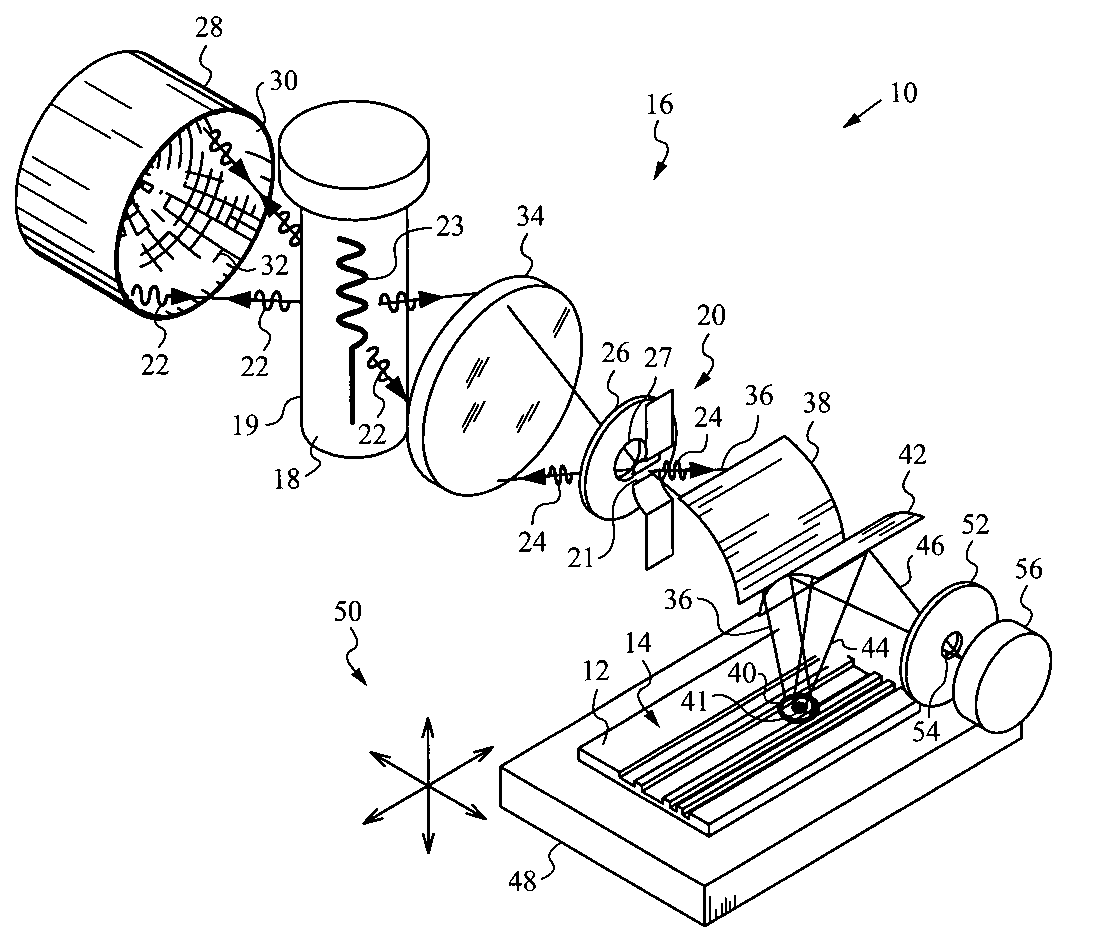
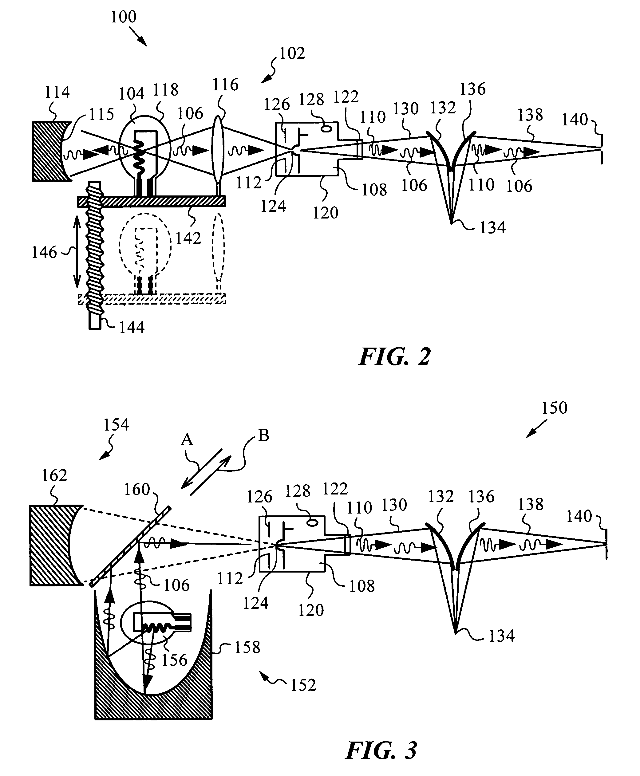
[0012]The objects and advantages of the invention are addressed by an apparatus for examining features of a sample with a broadband beam of light. The apparatus has a long-wavelength source for emitting a long-wavelength radiation and a short-wavelength source for emitting a short-wavelength radiation with a passage positioned between these two sources. A reflective beam combining optics is provided for shaping the long-wavelength radiation to enter the short-wavelength source via the passage and also for shaping the short-wavelength radiation that exits through the passage and propagates to the long-wavelength source. The reflective beam combining optics shapes the short-wavelength radiation such that it re-enters the short-wavelength source via the passage and in the process is combined with the long-wavelength radiation into the broadband beam that exits the short-wavelength source and propagates to the sample. The apparatus is further equipped with a beam steering optics for projecting the broadband beam to a spot on the sample. A scattered broadband radiation originating from the spot is intercepted by a beam intercept

Problems solved by technology

The combining of individual light sources to produce a single broadband output beam that satisfies the constraints imposed by the measurement method is a complex task.
Of course, in building a compound light source, it is not sufficient to just efficiently capture light from a single source.
Operating on broadband light beams places stringent constraints on the types of optics used.
In particular, refractive optics such as lenses, tend to perform poorly and all reflective optics may be preferred for such applications.
Unfortunately, none of the prior art solutions provides for a broadband light source that efficiently combines sources, provides a reasonably flat spectrum and achieves suitably high intensity at a correspondingly small spot size for examination of samples with small features.
However, in a broadband system these lenses add complication such as aberration and require frequent alignments.

Method used


Image

  • System and method for high intensity small spot optical metrology
  • System and method for high intensity small spot optical metrology
  • System and method for high intensity small spot optical metrology

Examples


Embodiment Construction

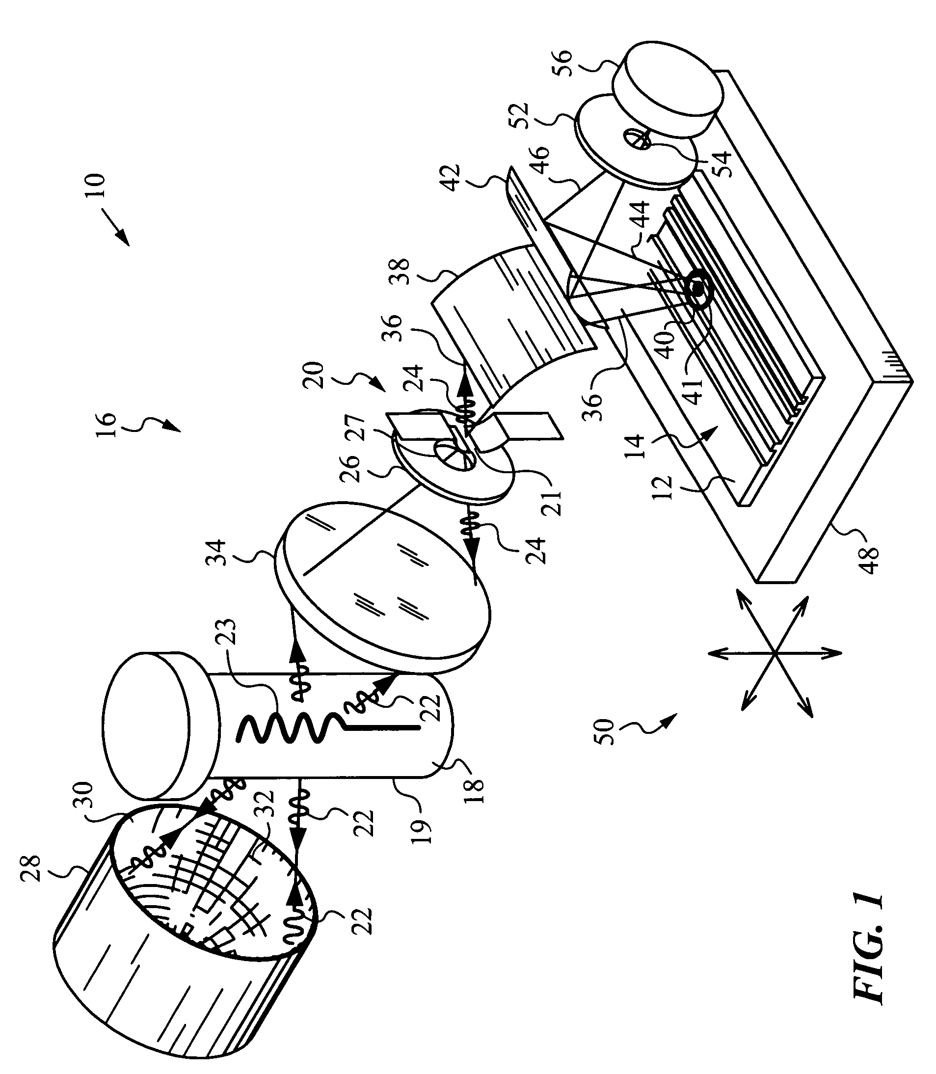
[0035]The present invention and its principles will be best understood by first referring to an apparatus 10 for examining features 14 of a sample 12, as shown in FIG. 1. Apparatus 10 has a compound source of light 16 that includes a long-wavelength source 18 for emitting a long-wavelength radiation 22 and a short-wavelength source 20 for emitting a short-wavelength radiation 24.

[0036]Long-wavelength source 18 is a lamp, e.g., a halogen lamp or a discharge lamp for emitting long-wavelength radiation 22 from a filament 23. Of course, other sources capable of emitting a long-wavelength radiation 22 spanning the appropriate bandwidth, i.e., visible to infrared, e.g., from about 250 nm to 900 nm or even up to 3,000 nm and above may also be used. The long-wavelength sources can themselves be compound, i.e., they may employ two or more separate emitters of different spectral portions of long-wavelength radiation 22. In any event, a casing 19 of lamp 18 is made of a wide-band transparent m...


PUM


Abstract

An apparatus and method for examining features of a sample with a broadband beam of light obtained from a long-wavelength source that may include two distinct emitters that emit a long-wavelength radiation and a short-wavelength source that emits a short-wavelength radiation. A passage is positioned between the sources and a reflective beam combining optics is provided for shaping the long-wavelength radiation to enter the short-wavelength source via the passage and also for shaping the short-wavelength radiation that exits through the passage and propagates toward the long-wavelength source. The reflective beam combining optics shape the short-wavelength radiation such that it re-enters the short-wavelength source via the passage and is combined with the long-wavelength radiation into the broadband beam that exits the short-wavelength source. A beam steering optics projects the broadband beam to a spot on the sample, and a scattered broadband radiation from the spot is intercepted and shaped to a broadband signal beam, which is passed through a sampling pinhole that passes a test portion of it on to a detector for optical examination; the test portion that is passed can correspond to a center portion of the spot.

Description

FIELD OF THE INVENTION[0001]This invention relates generally to systems and methods that employ a compound broadband light source for performing optical measurements with broadband beams that exhibit a high intensity and small spot size.BACKGROUND ART[0002]There are a number of applications and devices, which require for operation light that spans a broad wavelength spectrum. Since individual sources of light are only efficient in spanning portions of the broad wavelength spectrum needed, compound or composite light sources have been designed for these applications and devices. In particular, when the broad wavelength spectrum includes the ultra-violet (UV) and visible wavelengths two sources are usually combined into a broadband source covering this spectrum. This situation is encountered, for example, in scatterometry applications and devices where broad band light obtained from the compound source is used for determining optical properties of various materials as well as film thi...

Claims


Application Information

Patent Timeline
IPC IPC(8): G01B11/24
CPCG01J3/10G01J3/108G01N21/4738G01N21/9501G01N21/956G01N2021/4735
Inventor BALOOCH, MEHDIAHO, MARCAMIN, HOMANFOROUHI, ABDUL RAHIMWALSH, PHILLIPLI, GUOGUANG
Owner N & K TECH
Learn More