
Anisotropic collimation devices and related methods

a collimation device and anisotropic technology, applied in the field of light emitting devices, can solve problems such as efficiency reduction

Inactive Publication Date: 2008-03-25
LUMINUS DEVICES
View PDF70 Cites 11 Cited by
  • Summary
  • Abstract
  • Description
  • Claims
  • Application Information

AI Technical Summary

Problems solved by technology

In general, light extraction relates to device efficiency, since any light generated by the device which is not extracted can result in decreased efficiency.

Method used


Image

  • Anisotropic collimation devices and related methods
  • Anisotropic collimation devices and related methods
  • Anisotropic collimation devices and related methods

Examples


working examples

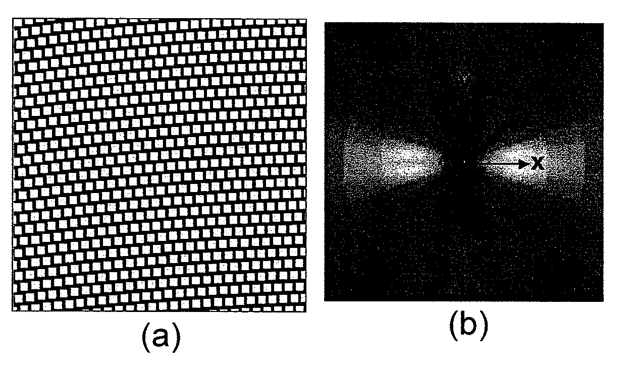
[0090]Some working examples are presented to illustrate various simulation results for LEDs incorporating some of the aforementioned patterns. It should be understood that these working examples do not limit the embodiments.

[0091]Hexagonal Pattern

[0092]Although collimated emission has been obtained in prior light-emitting devices having patterned surfaces (e.g., with hexagonal patterns), these emission profiles possessed an eight-fold symmetry, and were neither substantially isotropic nor anisotropic (e.g., having substantial collimation along only one axis in the emission surface plane). An example of such LEDs having a patterned surface that can provide a light emission profile that is more collimated than a Lambertian distribution is described in U.S. Patent Publication 2004 / 0207310A1 which is hereby incorporated by reference, which is based on U.S. patent application Ser. No. 10 / 724,029 filed on Nov. 26, 2003.

[0093]A hexagonal pattern of holes on the emission surface of a LED ha...


PUM


Abstract

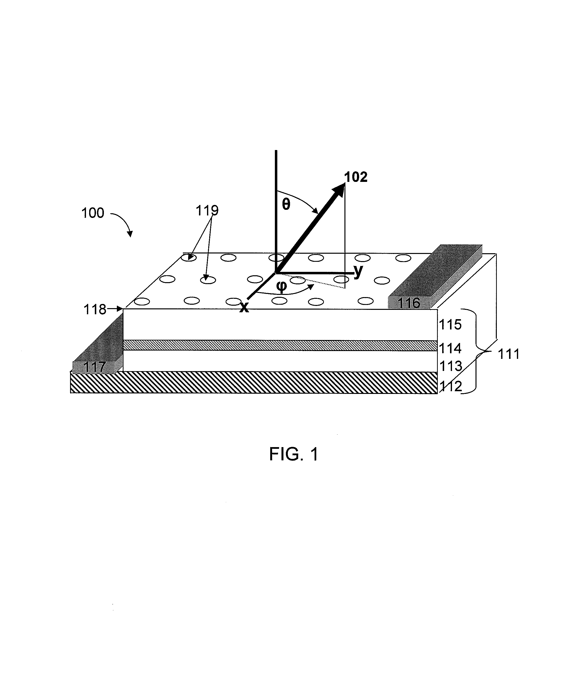
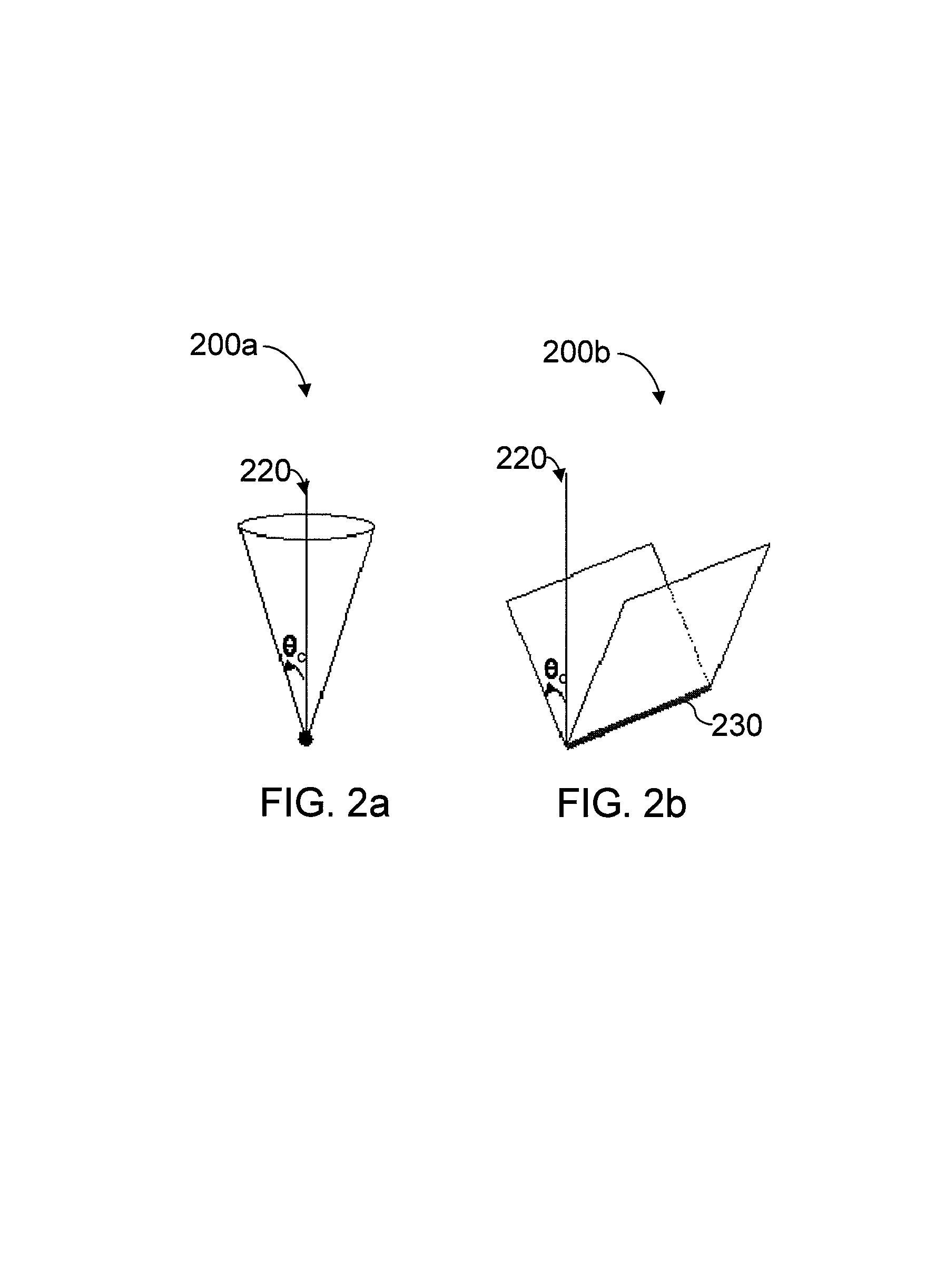
Devices, such as light-emitting devices (e.g., LEDs), and methods associated with such devices are provided. A light-emitting device designed to emit light may include an interface through which emitted light passes therethrough, wherein the interface has a dielectric function that varies spatially according to a pattern. The pattern may be arranged to provide anisotropic light emission characterized by an emission pattern on a far-field projection plane substantially parallel to the interface, wherein a first total light intensity along a first axis on the projection plane is at least 20% greater than a second total light intensity along a second axis on the projection plane. Alternatively, or additionally, the pattern may be arranged to provide anisotropic light emission characterized by a first total light emission on a first plane that is at least 20% greater than a second total light emission on a second plane, wherein the first and second planes are perpendicular to the interface, and wherein the first and second planes are also perpendicular to each other.

Description

RELATED APPLICATIONS[0001]This application claims priority under 35 U.S.C. § 119(e) to U.S. Provisional Application Ser. No. 60 / 727,753, filed on Oct. 17, 2005, and U.S. Provisional Application Ser. No. 60 / 737,136, filed on Nov. 16, 2005, which are herein incorporated by reference in their entirety.FIELD OF INVENTION[0002]The invention relates generally to light-emitting devices, as well as related components, systems, and methods, and more particularly to light-emitting devices having patterned interfaces.BACKGROUND[0003]There are a variety of light-emitting devices, such as light-emitting diodes (LEDs), laser diodes, and optical amplifiers, which can emit light and which may be used in various applications. The emitted light may be characterized by numerous metrics, including light extraction, collimation, and azimuthal isotropy. Light extraction is a measure of the amount of light emitted as compared to the amount of light generated within the light-emitting device. Collimation i...

Claims


Application Information

Patent Timeline
Patent Type & Authority Patents(United States)
IPC IPC(8): H01L33/00H01L33/20
CPCB82Y20/00G02B6/1225H01L33/20H01L2933/0083
Inventor ERCHAK, ALEXEI A.LIDORIKIS, ELEFTERIOSLIM, MICHAELNEMCHUCK, NIKOLAY I.VENEZIA, JO A.
Owner LUMINUS DEVICES
Learn More