Pipette and process for producing a pipette

Inactive Publication Date: 2008-03-18
BRAND GMBH CO KG
View PDF18 Cites 34 Cited by
  • Summary
  • Abstract
  • Description
  • Claims
  • Application Information

AI Technical Summary

Benefits of technology

[0013]The primary object of the present invention is to embody and develop a pipette of the type described initially such that a pipette shaft that is insensitive to tolerance is achieved, withdrawal forces are low when the pipette tip is ejected, and moreover, the above described problems with cleaning and the danger of contamination are eliminated.
[0014]The aforementioned object is achieved in the pipette of the type described initially by the sealing section which is made of an elastic-flexible plastic material which seals well being retentively molded directly to the plastic of the pipette shaft. In accordance with the invention, the sealing section is not made of a separate part, but is retentively molded directly on the thermoplastic of the pipette shaft. This has the advantage that the sealing section is captively held and is not displaced when the pipette tip is slipped on. In this way, a spongy stop feeling for the user can be avoided. Nor is a gap formed by the displacement of the sealing section, so that there is no contamination. A second sealing site between the recess of the pipette shaft and the sealing section is unnecessary. The boundary layer is sealed and neither dirt nor liquid can penetrate.
[0016]It is especially advantageous if the approach of the invention is implemented by the pipette shaft with the sealing section being made, cost-efficiently, without installation effort as a dual component plastic, injection molded part.

Problems solved by technology

Both individual pipettes and also multichannel pipettes or larger pipetting devices are subject to the problem that the pipette tip must be slipped on the pipette shaft, forming a seal but, at the same time, the tip must be able to be pushed off from the pipette shaft by means of mechanical ejection with as little expenditure of force as possible.
High withdrawal forces of the pipette tip require a high expenditure of force when the ejector sleeve is actuated.
The problem of withdrawal forces is especially great in pipettes known to date in which the pipette shaft is produced from a relatively hard, wear-resistant plastic and the tip is produced from somewhat less hard, deformable plastic, especially polypropylene.
The attachment section of pipette shaft can be easily damaged.
However, here, there is the problem of cleaning and the structurally comparatively great effort for the actuating mechanism.
Moreover, the existence of gaps is a problem.
In any case, the separate formation of the sealing section is a problem in the slipped-on sealing element with respect to gap formation, cleaning possibilities and danger of contamination in the same way as in the above explained prior art.
Another problem in using different generic pipette tips of different manufacturers in conjunction with the known ejector sleeve is that the effective axial length of the slip-on section of the pipette tip is different for the different pipette tips.
In the prior art, it has already been recognized that there are cases in which the pipette ejector sleeve which is actuated by the ejector only just touches the edge of the pipette tip, or in any case, the pipette tip can no longer be effectively ejected.

Method used


Image

  • Pipette and process for producing a pipette
  • Pipette and process for producing a pipette
  • Pipette and process for producing a pipette

Examples


Embodiment Construction

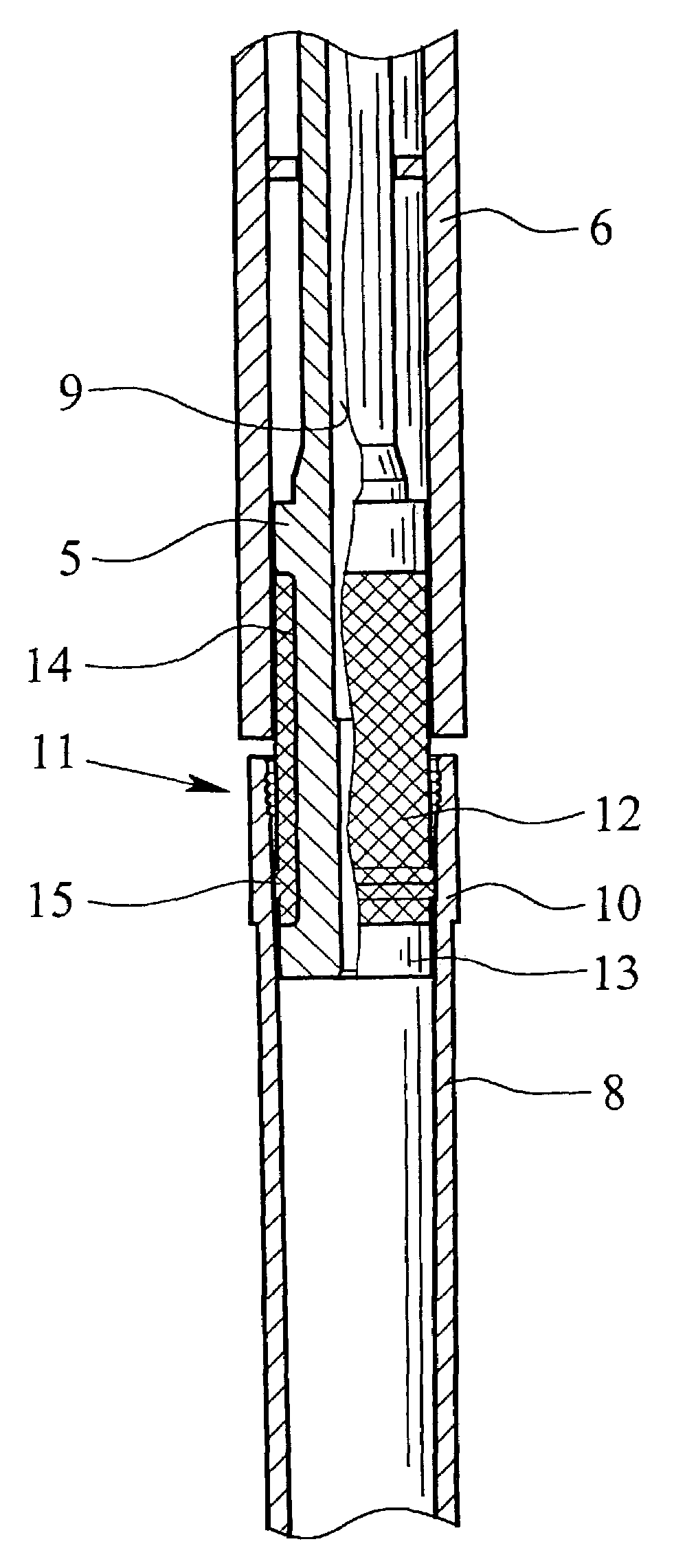
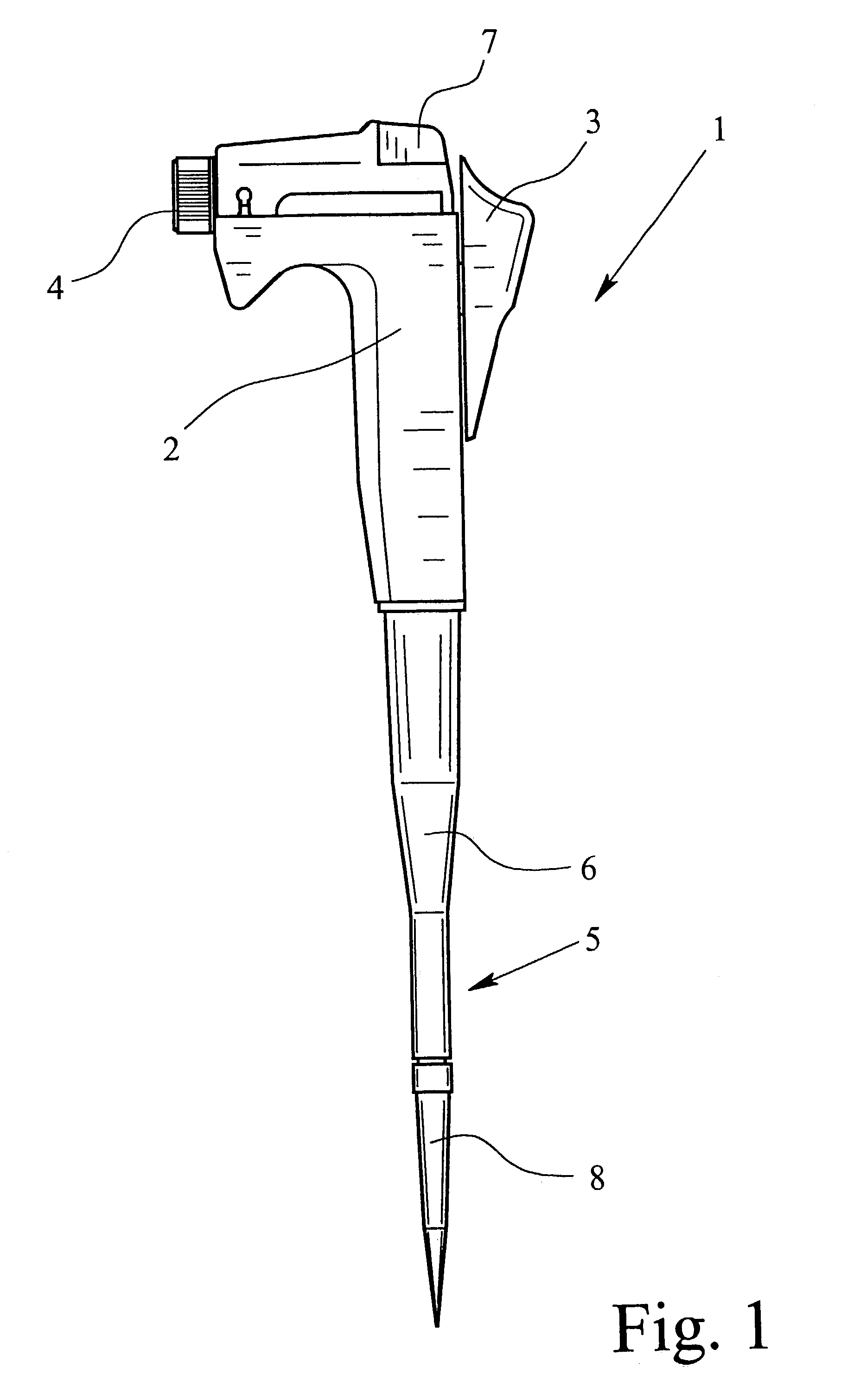
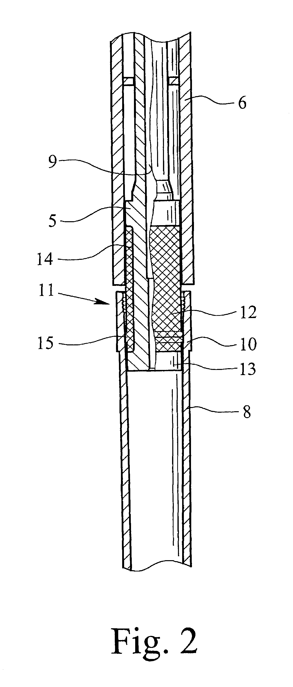
[0022]FIG. 1 a single channel pipette 1. As has already been explained in the general part of the specification, the teaching of this invention is not limited to a single channel pipette, but rather it can, likewise, be used for multi-channel pipettes (compare German Patent Application DE 100 13 511 A1) and also for mechanical pipetting means. The teaching of the invention is the coupling of the pipette tip to the pipette shaft of a pipette.

[0023]German Patent Application DE 100 13 511 A1 relates to structural approaches to interchangeability of the pipette shaft in a multi-channel pipetting means. These structural approaches can also be used in a multi-channel pipette which is made according to the teaching of this application.

[0024]FIG. 1 shows the pipette 1 with a handle 2, a manual actuation button which constitutes the actuator 3 of the pipette, an adjustment element 4 for adjusting the volume to be pipetted and / or for calibration of the pipette 1, and a pipette shaft 5. An eje...


PUM

PropertyMeasurementUnit
Lengthaaaaaaaaaa
Diameteraaaaaaaaaa
Flexibilityaaaaaaaaaa

Abstract

A pipette has a preferably thermoplastic pipette shaft, for slipping on a likewise preferably thermoplastic pipette tip, has a slip-on section which opens at least slightly conically, and an attachment section which is formed on the lower end of the pipette shaft and onto which the slip-on section of the pipette tip is slipped. A sealing section which is made of an elastically-flexible plastic material which seals well with low withdrawal forces is provided on the attachment section. Furthermore, preferably, a fixing section is formed on the plastic material of the attachment section of the pipette shaft at a location that is axially offset relative to the sealing section. The sealing section of elastic-flexible plastic material is molded directly, retentively, on the preferably thermoplastic material of the pipette shaft.

Description

BACKGROUND OF THE INVENTION[0001]1. Field of the Invention[0002]The subject matter of the invention is a pipette with a pipette shaft which has been produced preferably from thermoplastic onto which a likewise plastic pipette tip is slipped. More specifically, the invention relates to a pipette which has an ejector sleeve which surrounds the pipette shaft and an ejector actuator, the pipette shaft being made for slipping on a likewise plastic pipette tip which has a preferably slightly conically opening slip-on section, the pipette also being provided with an attachment section which is formed on the lower end of the pipette shaft and onto which the slip-on section of the pipette tip is slipped. A sealing section is provided on the attachment section which is formed of an elastically-flexible plastic material which seals well with low withdrawal forces. The ejector sleeve is pushed down axially relative to the pipette shaft by the ejector actuator in order to eject the pipette tip w...

Claims


Application Information

Patent Timeline
IPC IPC(8): B01L3/02
CPCB01L3/0279
Inventor MAHLER, PETERREMPT, RENATEPROKOPP, PETER
Owner BRAND GMBH CO KG
Why Eureka
Try Eureka