Bar feeder

a feeder and bar technology, applied in the field of bar feeders, can solve the problems of machine failure, inconvenient use of aforesaid conventional bar feeders, vibration and noise, etc., and achieve the effect of reducing vibration and nois

Inactive Publication Date: 2008-03-18
BARLOAD MACHINE
View PDF8 Cites 2 Cited by
  • Summary
  • Abstract
  • Description
  • Claims
  • Application Information

AI Technical Summary

Benefits of technology

[0007]The present invention has been accomplished under the circumstances in view. It is one object of the present invention to provide a bar feeder, which is capable of reducing vibration and noise during its working.
[0008]It is another object of the present invention to provide a bar feeder, which reduces the risk of machine failure and enhances the convenient of use of the machine.

Problems solved by technology

However, because there is a gap between the projecting rod and the pushing rod, vibration and noise are produced when projecting the bar material into the automatic lathe for processing.
Further, the gap between the projecting rod and the pushing rod may cause accidental engagement between the pushing rod and the feeder tube or chain during movement of the pushing rod, resulting in a machine failure.
Therefore, the aforesaid conventional bar feeder is not convenient in use.

Method used


Image

  • Bar feeder
  • Bar feeder
  • Bar feeder

Examples


Embodiment Construction

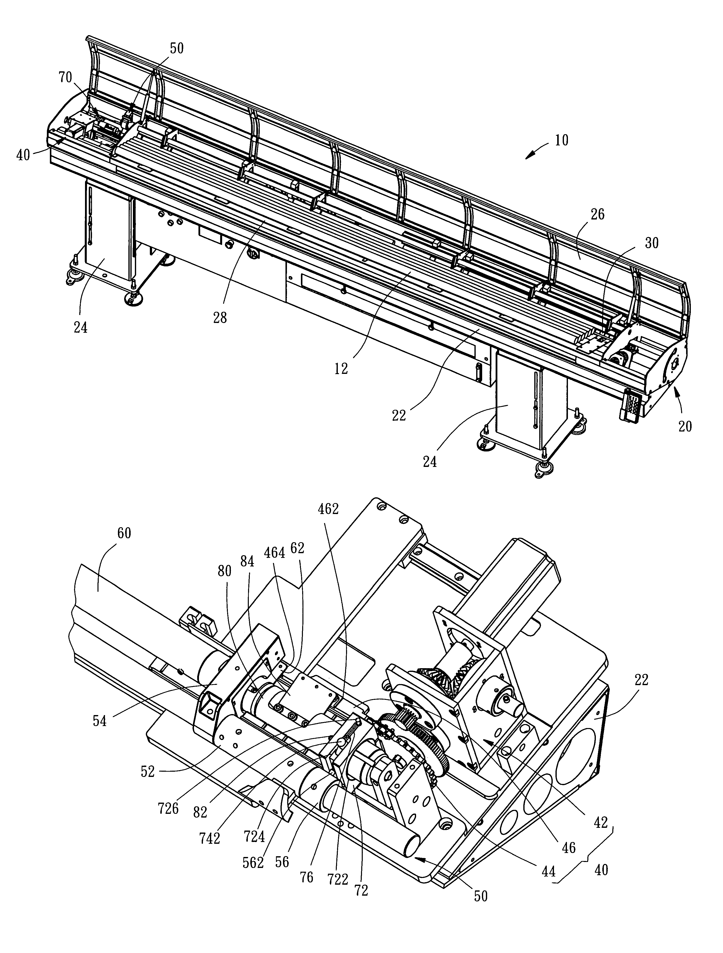
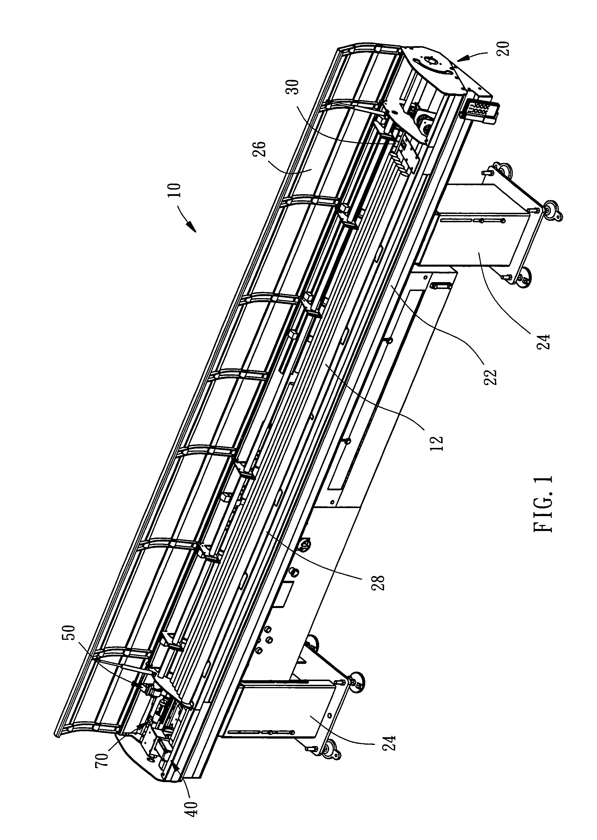
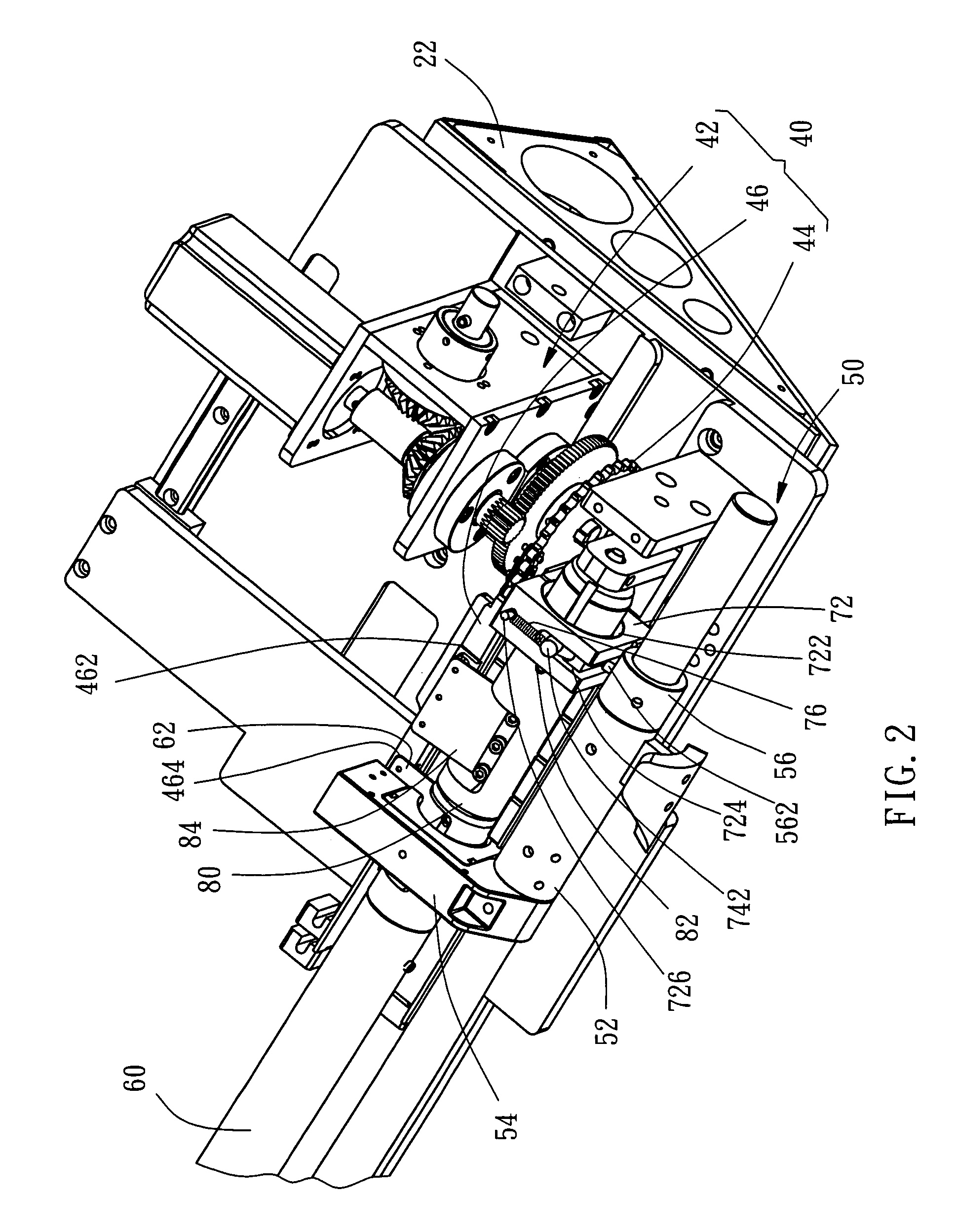
[0018]As shown in FIGS. 1 and 2, a bar feeder 10 in accordance with a preferred embodiment of the present invention comprises a machine base 20, a feeder tube 30, a transmission mechanism 40, a driving mechanism 50, a projecting rod 60, a driven mechanism 70, and a pushing rod 80.

[0019]The machine base 20 comprises a worktable 22, two stands 22 provided at the bottom side of the worktable 22 for supporting the worktable 22 on the floor, a top cover 26 provided at the top side of the worktable 22 and adapted to prohibit the operator from touching the internal parts of the bar feeder 10 accidentally during operation of the bar feeder 10, and a material rack 28 for holding bar materials 12.

[0020]The feeder tube 30 is mounted on the worktable 22 of the machine base 20 and adapted to receive the bar material 12 from the material rack 28 for feeding to a processing machine, for example, an automatic lathe (not shown) for processing.

[0021]The transmission mechanism 40 is mounted in one end...


PUM

PropertyMeasurementUnit
rotationaaaaaaaaaa
transmission mechanismaaaaaaaaaa
timeaaaaaaaaaa

Abstract

A bar feeder includes a feeder tube mounted on a machine base, a transmission mechanism, a driving mechanism having a rotary shaft, a projecting rod connected to the driving mechanism and rotatable with the rotary shaft to engage or disengage from the transmission mechanism, a pushing rod, and a driven mechanism rotatable with the rotary shaft to move the pushing rod into engagement or away from the transmission mechanism. When the pushing rod and the transmission mechanism are coupled together, the pushing rod is movable along the feeder tube, and the projecting rod is disengaged from the transmission mechanism and moved away from the feeder tube. When the pushing rod and the transmission mechanism are disconnected, the pushing rod is not movable along the feeder tube, and the projecting rod is coupled to the transmission mechanism and movable along the feeder tube.

Description

BACKGROUND OF THE INVENTION[0001]1. Field of the Invention[0002]The present invention relates to a bar material feeding machine for feeding a bar material into a processing machine, such as a lathe, and particularly, to a bar feeder, which is capable of reducing vibration and noise during its working.[0003]2. Description of the Related Art[0004]In a conventional bar feeder and lathe system, the bar feeder is provided at the rear side of the automatic lathe and adapted to feed a bar material into the automatic lathe for processing.[0005]A conventional bar feeder generally comprises a rotary shaft, a transmission mechanism, a pushing rod, and a projecting rod. The rotary shaft has a coupling member. The transmission mechanism comprises a chain. The pushing rod is fixedly connected to the chain. The projecting rod is coupled to the coupling member of the rotary shaft and rotatable with the rotary shaft between a first position where the projecting rod is engaged with the chain and a se...

Claims


Application Information

Patent Timeline
Patent Type & Authority Patents(United States)
IPC IPC(8): B23B3/00B23B13/00
CPCB23B13/08Y10T82/2514Y10T82/2518Y10T82/2521
Inventor LU, FANG-CHIN
Owner BARLOAD MACHINE
Why Eureka
Try Eureka