Motor-operated fan for air cushion table

a motor-operated fan and air cushion technology, which is applied in the direction of liquid fuel engines, marine propulsion, vessel construction, etc., can solve the problems of motor vibration and noise during operation, reduce the playing effect of players, etc., and achieve the effect of reducing vibration and noise of motor-operated fans, reducing vibration and noise, and increasing air flow

Inactive Publication Date: 2006-06-08
HOU CHIN JUNG
View PDF3 Cites 1 Cited by
  • Summary
  • Abstract
  • Description
  • Claims
  • Application Information

AI Technical Summary

Benefits of technology

[0007] Another objective of the present invention is to provide a motor-operated fan, wherein the impeller has a plurality of blades and a plurality of auxiliary blades to produce a larger air flow when the impeller is rotated so as to push a ball located above the air cushion table, so that the ball is moved above the air cushion table in an irregular manner at a higher speed, thereby providing an amusement playing effect for players.
[0008] A further objective of the present invention is to provide a motor-operated fan, wherein the motor is hidden in the housing completely, thereby greatly reducing vibration and noise of the motor-operated fan.
[0009] A further objective of the present invention is to provide a motor-operated fan, wherein the impeller has a plurality of blades and a plurality of auxiliary blades to produce a larger air flow, thereby enhancing the heat dissipation effect of the motor-operated fan.

Problems solved by technology

However, the air flow produced by the impeller is not large enough to push the ball to move at a higher speed, thereby greatly decreasing the playing effect for the players.
In addition, the motor produces vibration and noise during operation.

Method used


Image

  • Motor-operated fan for air cushion table
  • Motor-operated fan for air cushion table
  • Motor-operated fan for air cushion table

Examples


Embodiment Construction

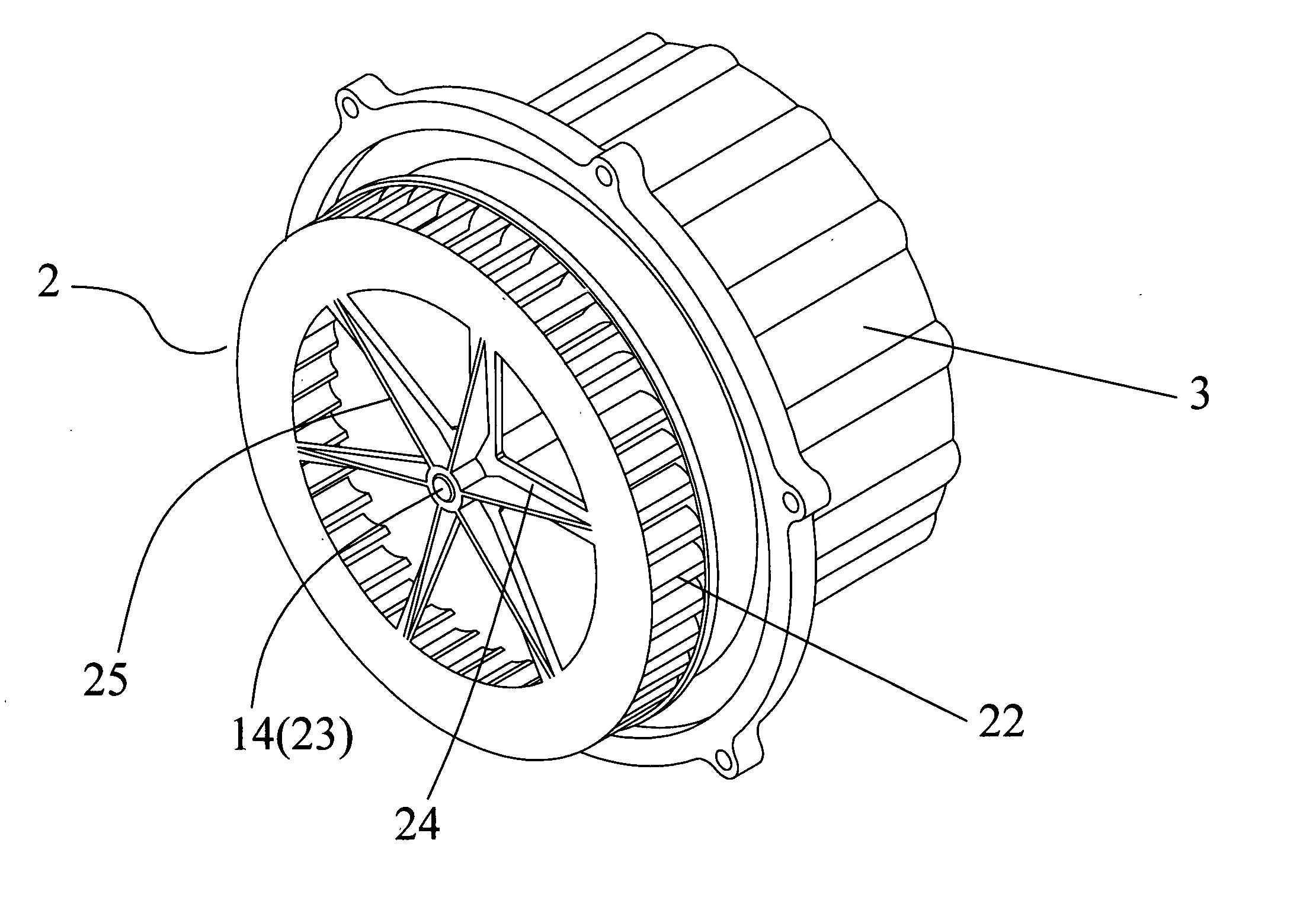
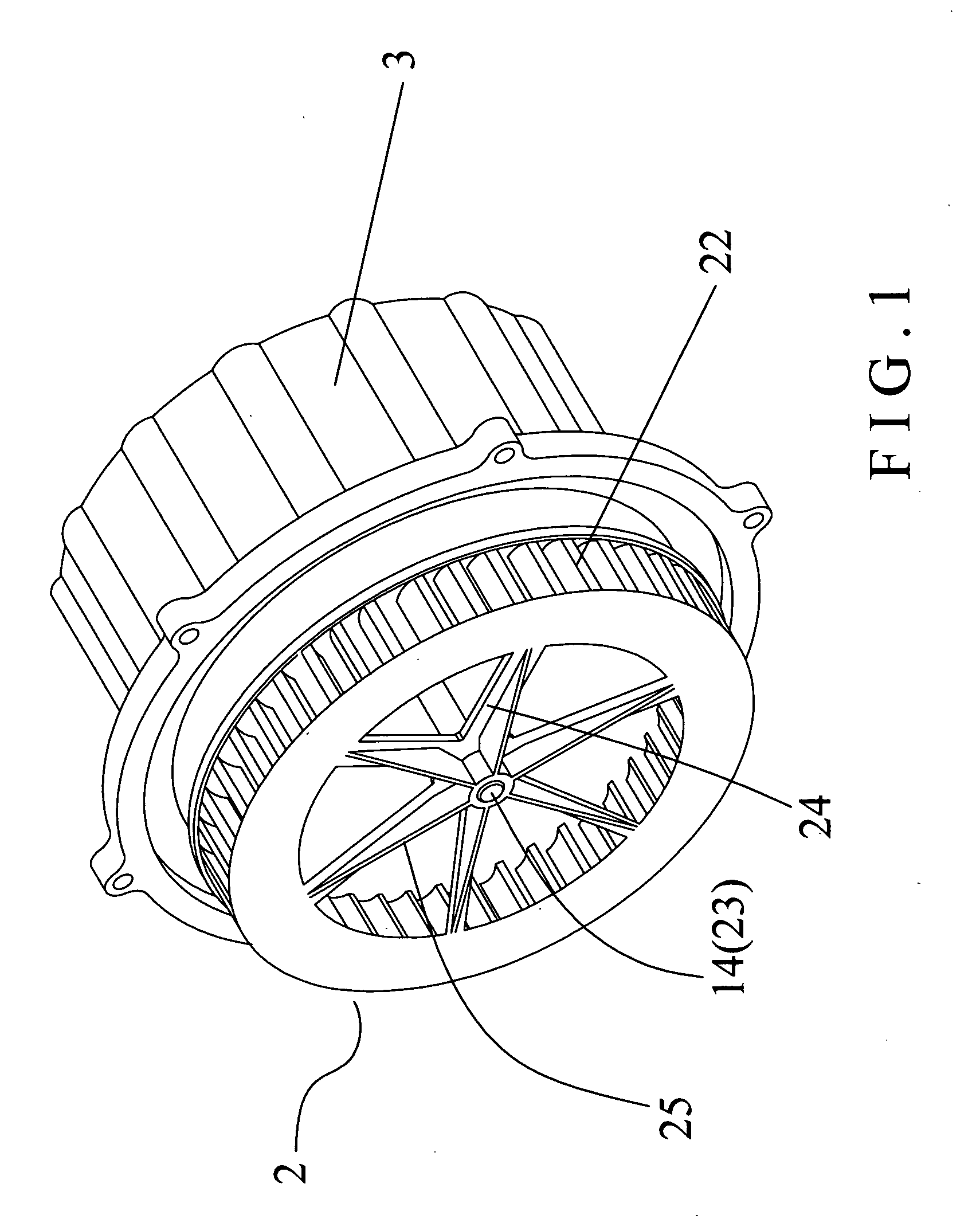
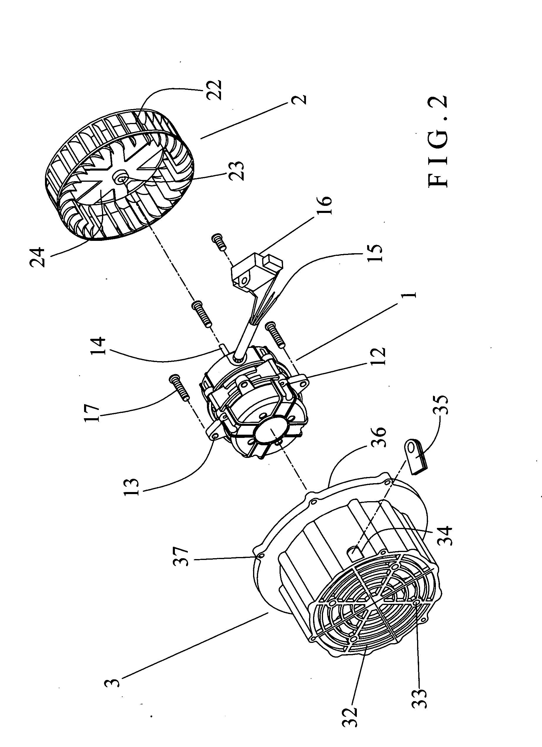
[0014] Referring to the drawings and initially to FIGS. 1 and 2, a motor-operated fan in accordance with the preferred embodiment of the present invention comprises a housing 3, a motor 1 secured in the housing 3, and an impeller 2 rotatably mounted on the housing 3 and rotated by the motor 1.

[0015] The housing 3 is a circular recessed body and has a closed wall formed with a net-shaped plate 32 and an opened wall formed with a radially outward extended annular flange 36 having a plurality of mounting holes 37 for mounting the housing 3 to an air cushion table 4 as shown in FIG. 3. The net-shaped plate 32 of the housing 3 is arranged in a radiating manner and has a plurality of screw bores 33. The housing 3 has a peripheral wall formed with a U-shaped slot 34.

[0016] The motor 1 has a central portion provided with a rotation shaft 14. The motor 1 has a peripheral wall provided with a plurality of fixing ears 12 each formed with a through hole 13, and the motor-operated fan further ...


PUM


Abstract

A motor-operated fan includes a housing, a motor secured in the housing, and an impeller rotatably mounted on the housing and rotated by the motor. Thus, the impeller has a plurality of blades and a plurality of auxiliary blades to produce a larger air flow when the impeller is rotated so as to push a ball located above the air cushion table, so that the ball is moved above the air cushion table in an irregular manner at a higher speed, thereby providing an amusement playing effect for players.

Description

BACKGROUND OF THE INVENTION [0001] 1. Field of the Invention [0002] The present invention relates to a motor-operated fan, and more particularly to a motor-operated fan for an air cushion table to provide an amusement effect for players. [0003] 2. Description of the Related Art [0004] A conventional motor-operated fan for an air cushion table comprises a motor, and an impeller. Thus, when the motor is operated, the rotation shaft of the motor is rotated to rotate the impeller whose rotation produces an upward air flow that is forced to pass through air vents located at the top of the air cushion table to push a ball located above the air cushion table, so that the ball is moved above the air cushion table in an irregular manner, thereby providing an amusement playing effect for players. However, the air flow produced by the impeller is not large enough to push the ball to move at a higher speed, thereby greatly decreasing the playing effect for the players. In addition, the motor pr...

Claims


Application Information

Patent Timeline
Patent Type & Authority Applications(United States)
IPC IPC(8): F04D19/00
CPCF04D29/282
Inventor HOU, CHIN-JUNG
Owner HOU CHIN JUNG
Why Eureka
Try Eureka