Eureka AIR delivers breakthrough ideas for toughest innovation challenges, trusted by R&D personnel around the world.

Swash plate compressor

a compressor and plate technology, applied in the direction of machines/engines, mechanical equipment, positive displacement liquid engines, etc., can solve the problems of non-uniform abrasion of the piston and the inner circumferential surface of the cylinder bore, inability to sufficiently lessen the side force exerted on the piston, and the cylinder bore, so as to reduce vibration and noise, reduce the non-uniform abrasion of the piston

Inactive Publication Date: 2005-07-05
SANDEN CORP
View PDF8 Cites 2 Cited by
  • Summary
  • Abstract
  • Description
  • Claims
  • Application Information

AI Technical Summary

Benefits of technology

[0014]An object of the present invention is to provide a swash plate compressor capable of reducing non-uniform abrasion of a piston and a cylinder bore due to side force exerted on the piston, or decreasing vibration and noise thereof.
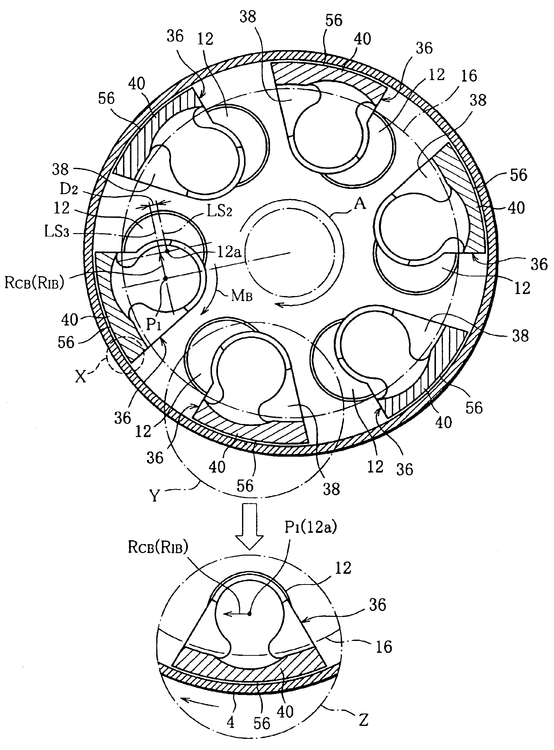
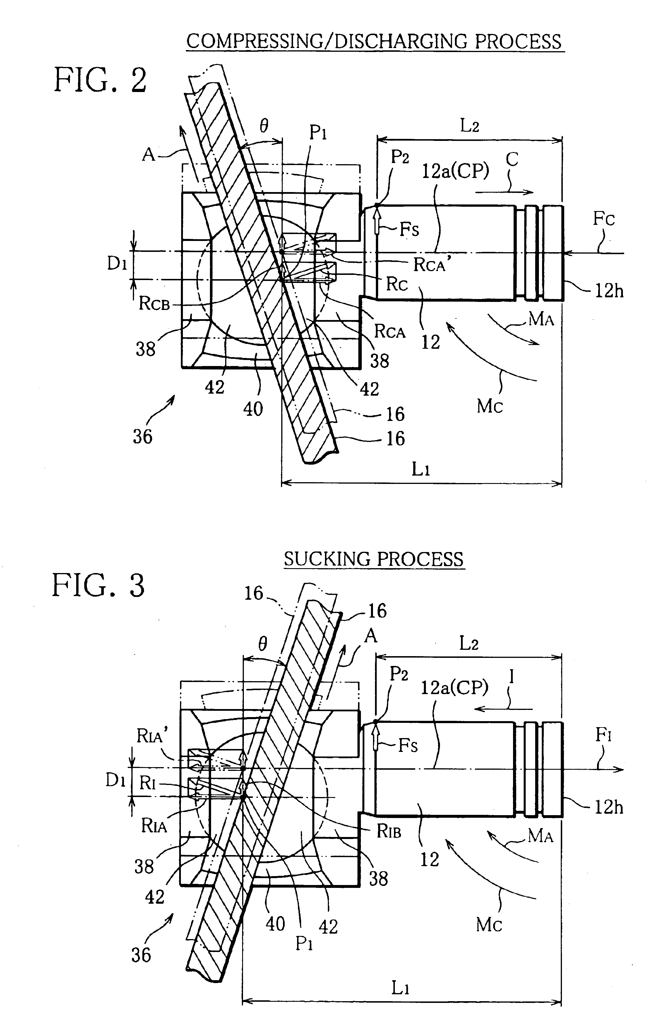
[0022]On the other hand, in the case that the central point of the shoe deviates inwardly from the piston axis in the radial direction of the swash plate, the reactive force or the side force gives the piston a moment that makes the piston rotate around the axis thereof. Accordingly, during the rotation of the swash plate, a leading or trailing edge of the stopper face of the tail of the piston in view of the rotating direction of the swash plate is pressed against the inner circumferential surface of the swash plate chamber. The leading or trailing edge of the stopper face is, therefore, maintained in constant contact with the inner circumferential surface of the swash plate chamber. As a result, the leading or trailing edge of the stopper face never collides with the inner circumferential surface of the swash plate chamber, thus reducing the vibration and noise of the compressor.
[0023]Specifically, the central point of the shoe located off the common plane is obtained by shifting the tail of the piston from the piston axis in the radial direction of the piston. The piston with such a tail does not require more working-process time and cost than a normal piston does.

Problems solved by technology

Therefore, the side force causes the piston to press against a part of the inner circumferential surface of the cylinder bore, thus creating non-uniform abrasion of the piston and the inner circumferential surface of the cylinder bore.
Accordingly, even if the annular grooves are formed in the swash plate, it is impossible to sufficiently lessen the side force exerted on the piston, that is, the non-uniform abrasion of the piston and the cylinder bore.
It is very difficult, however, to bring the inner circumferential surface of the crank chamber and the stopper face into closely contact with each other, so that a small gap left-between the inner circumferential surface of the crank chamber and the stopper face is unavoidable.
Such collision not only vibrates the compressor but also increases the noise of the compressor.

Method used


Image

  • Swash plate compressor
  • Swash plate compressor
  • Swash plate compressor

Examples


Embodiment Construction

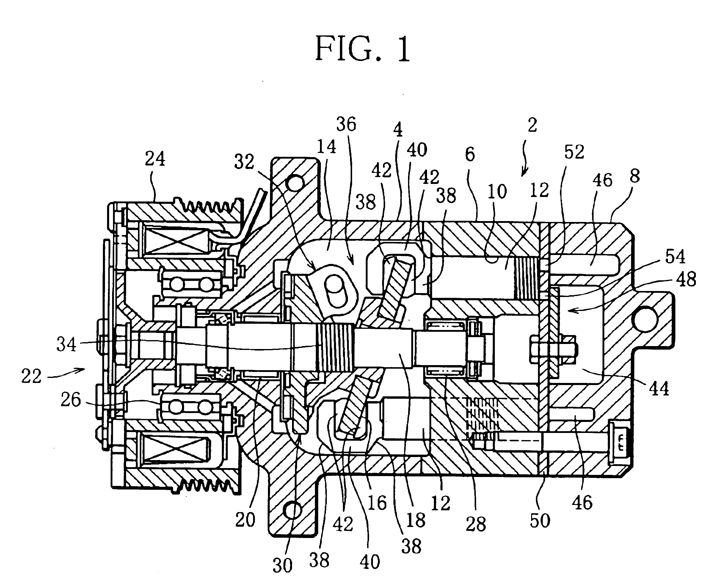
[0030]A swash plate compressor illustrated in FIG. 1 is incorporated into a refrigerating circuit (not shown) of an air-conditioning system for a vehicle. The swash plate compressor compresses a refrigerant as working fluid utilized in the refrigerating circuit and supplies a high-pressure refrigerant to the refrigerating circuit.

[0031]The compressor comprises a cylindrical housing 2 having a crankcase 4, a cylinder block 6 and a cylinder head 8, that are arranged in order from the left side in FIG. 1.

[0032]The cylinder block 6 has a plurality of cylinder bores 10 therein. The cylinder bores 10 are arranged at regular intervals in a circumferential direction of the cylinder block 6. Inserted into each cylinder bore 10 is a piston 12 capable of reciprocating in the cylinder bore 10.

[0033]The crankcase 4 defines therein a swash plate chamber or a crank chamber 14, which accommodates a drive device. The drive device includes a swash plate 16 mounted on a drive shaft 18. The drive shaft...


PUM


Abstract

A swash plate compressor comprises a swash plate rotated by a drive shaft and a piston that reciprocates in a cylinder bore by the rotation of the swash plate. The piston includes a tail and a pair of shoes retained in the tail. The shoes sandwich an outer periphery of the swash plate. Each shoe has a receiving face for receiving the outer periphery of the swash plate. A central point of the receiving face is located off a common plane including an axis of the piston and that of the drive shaft.

Description

[0001]This nonprovisional application claims priority under 35 U.S.C. § 119(a) on Patent Application No. 2002-356393 filed in Japan on Dec. 9, 2002, the entire contents of which are hereby incorporated by reference.BACKGROUND OF THE INVENTION[0002]1. Field of the Invention[0003]The present invention relates to a swash plate compressor incorporated into a refrigerating circuit of an air-conditioning system for a vehicle.[0004]2. Description of the Related Art[0005]A swash plate compressor of this type is disclosed, for example, in Unexamined Japanese Patent Application No. 5-10255. This publicly known compressor includes a cylinder block in which a plurality of cylinder bores are defined and pistons inserted in their respective cylinder bores. These pistons reciprocate in the cylinder bores in response to the rotation of a swash plate. The reciprocation of the pistons performs the process of sucking a refrigerant used in the refrigerating circuit and the process of compressing / discha...

Claims


Application Information

Patent Timeline
IPC IPC(8): F04B27/08F04B39/00F04B27/10
CPCF04B27/0878
Inventor IIZUKA, JIRO
Owner SANDEN CORP
Why Eureka
Eureka Blog
Learn More